The following discussion is part of an occasional series showcasing the ISA Mentor Program, authored by Greg McMillan, industry consultant, author of numerous process control books, 2010 ISA Life Achievement Award recipient, and retired Senior Fellow from Solutia, Inc. (now Eastman Chemical). Greg will be posting questions and responses from the ISA Mentor Program, with contributions from program participants.
Christine Joy Panganiban has more than eight years of industry experience in instrumentation and control (I&C). She has a strong foundation in electronics engineering with extensive experience in programming, testing, and commissioning. Her engineering forte is in PLC/SCADA systems and she is skilled in troubleshooting. She has been a member of the ISA Mentor Program since 2017.
Christine Joy Panganiban’s Question
What is the best way to install a DP in level applications with a wet leg?
An example for a boiler drum level in an ISA Standard shows the reference leg connected to the DP low pressure (LP) side and the drum level connected to the DP high pressure (HP) side. But the main and subsequent replies to this question in magazine say the reference leg with condensate (wet leg) is connected to the HP side, since the wet leg pressure is higher than the pressure for level. The need for signal reversal is mentioned.
We have been arguing about this in our plant for a deaerator tank level measurement.
Greg McMillan’s Answer
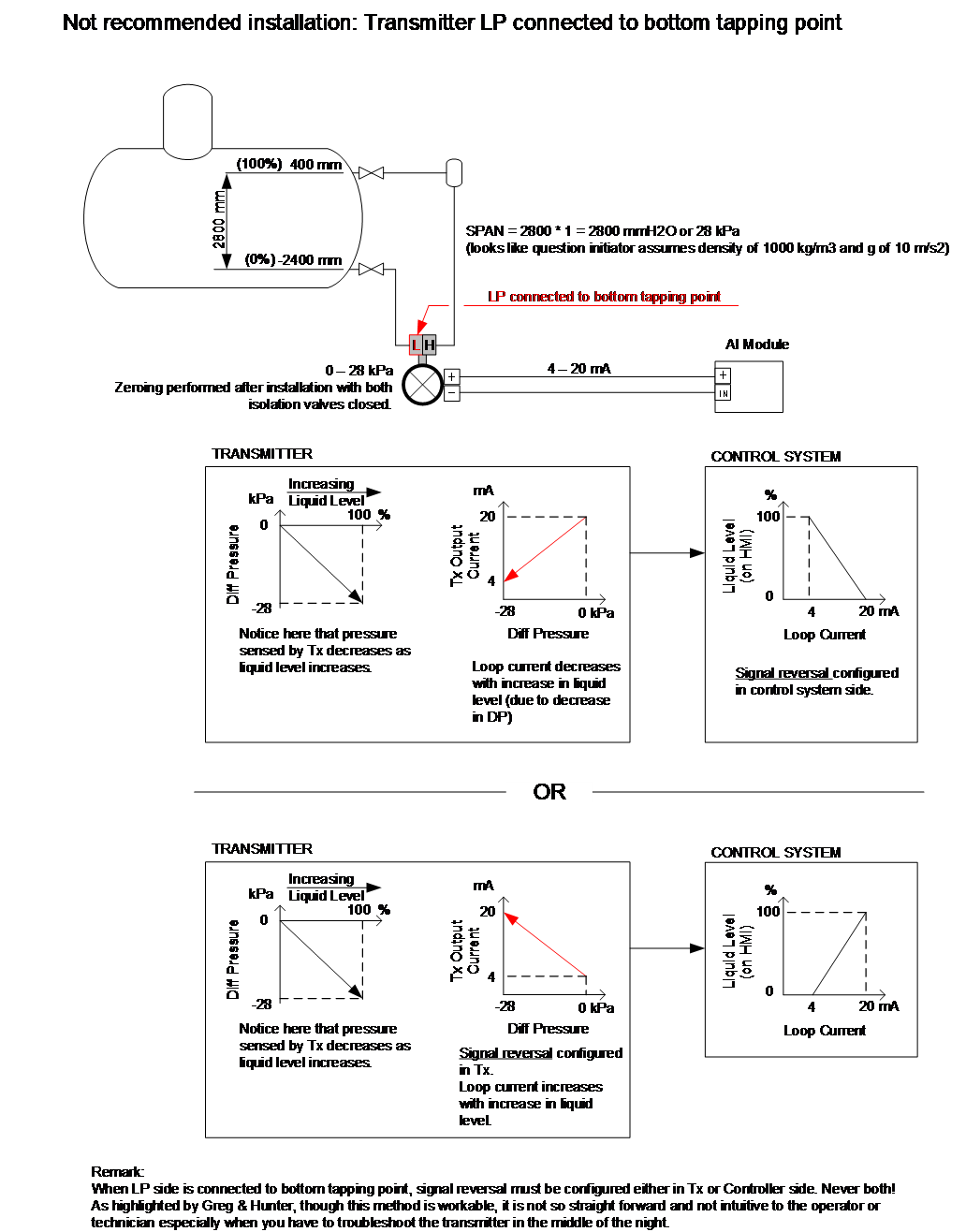
If you connect the wet leg to the HP side, you must have a reverse acting DP or reverse the signal somewhere before it gets to the operator interface and PID controller, which can be confusing during maintenance and calibration checks. If you have a HART or Foundation fieldbus smart level transmitter that enables you to do a sufficient wet leg compensation, you can then go with the LP connected to the wet leg and the HP connected to the bottom of the tank (like level transmitters, where the reference leg is dry and simply used to compensate for vessel pressure).
You need to verify your DP has sufficient wet leg compensation so you can connect the HP to the bottom of the tank. Also, calibration checks then have a reference leg and reservoir pressure put on the LP side and a filled sensing leg pressure, vessel pressure, and liquid head on the HP side to correspond to 0% level.
You obviously need to make sure that the wet leg top reservoir level never changes, and wet leg line never freezes. Realize that using a DP for level measurement will not show the actual level height due to changes in density and bubbles (e.g., shrink and swell). A radar measurement is the most precise and fool-proof measurement of actual surface level. Radar is expensive, but in the long run may be worth it in terms of less maintenance and confusion and being able to operate closer to a level constraint. Non-contacting radar, also known as free space radar, would only require a nozzle on the top of the tank with an unobstructed view.
Hunter Vegas’s Answer
First let me say I have never seen anyone tie the wet leg (upper connection) to the high side of the transmitter. I was amazed that Bela and Dick made that suggestion (at first, I was thinking they made a mistake in the article!). I totally agree with Greg that connecting the high tap to the bottom of the drum makes the most sense. A rising level generates a rising signal, which makes it much more intuitive to work on. Also, a failed signal shows a “low” level, which is what you want to see (I will warn you that this usually results in a strange calibration—something like -30” to -3” = 0 to 100%).
I will also echo Greg’s suggestion that you consider radar instead. Several manufacturers have created units that handle high temperatures and perform well. A guided wave unit may be a better option, but there are non-contacting radars that can work as well (the best choice will depend on the pressure/temperature you are running. Talk to your vendor to choose the right model).
If you are going with a DP transmitter, then I would warn you about several things:
1) Operating Pressure: A DP transmitter will read accurately only when it is operating at normal operating pressures and temperatures. This is because the specific gravity of the liquid in the tank goes into the calibration of the device and the specific gravity is determined by the pressure/temperature of the liquid. Therefore, if the tank isn’t at normal operating conditions, the level transmitter reading will likely be wrong (I’ve had operators complaining about boiler levels on start-up and demand they be recalibrated. Of course, if we calibrated them at that point, they would have been wrong when the boiler was up to pressure. Once the boiler got to normal operating conditions, the level was accurate).
2) Heat Tracing on the Static Lines: If the transmitter is mounted outside, then the static lines will need some kind of freeze protection, and this can be a source of major headaches. The specific gravity of the wet leg depends on the temperature of the heat trace, which also shifts the calibration. If you have heat trace, leave it on year-round. I have seen cases where plants turn the heat trace off in the summer and this can shift the level reading a couple of inches.
3) Coming Up with the Exact Calibration Can Be Tricky: If you are unsure how that is done, I am able to draw up the details for that.
I hope this answers your question!
Christine Joy Panganiban’s Follow-Up
We have a Rosemount 3051S with a calibration range of 0-28kPa and DCS Range -2400 -400mm. I can't convince one of the team members though; he is insisting that the pressure in the wet leg is higher because of its position (high head, or should I say level).
He said we can just reverse the signal going to the DCS so that it will indicate correctly. What are your thoughts on this?
Hunter Vegas’s Reply
Yes, the top tap has a higher pressure than the low tap, but it still works the same. You just shift the zero to compensate. You can certainly hook it up backwards (high tap on high side, low tap on low side) and then flip the signal again in the DCS to make it read correctly, but to what end? You could also stand on your head to paint a picture and then flip the canvas over to make it right, but it seems like a painful way to go about making art!
You also have the issue of the signal failing the wrong way. In either a deaerator or boiler, I would want a failed transmitter to read zero level rather than full.
Greg McMillan’s Reply
I agree with Hunter. Signal failure is a big concern. Also, while some people may understand the use of the signal reversal, technicians, configuration engineers, operators, and process engineers may be confused. I also wonder whether all the plant people and contractors in the production unit now and in the future including upgrades and expansions will recognize the need for signal reversal and track down the location of the signal reversal. The person who wants signal reversal may not be there in the middle of the night when the transmitter needs maintenance or in a future project.
Mike Laspisa’s Reply
Maybe it is an outdated approach to use HP side connected to wet leg with current digital DP cell transmitters, but it was the preferred approach at my plant in 2017 to match the boilers installed in 2002 and 2004. If a plant has standardized on the old practice to use HP side connected to wet leg, it may be problematic to start going with a new practice. The plant may choose to stay with old practice if DP failure causing max upscale reading is not an issue and the old practice is well documented with alerts, so that new plant people and contractors are onboard.
Zhafran Hamid’s Reply
I had once worked on a rejuvenation project for an old plant. For the DP Level transmitter replacement, we encountered some existing transmitters having low pressure (LP) ports connected to the vessel bottom tapping point. Tony Kuphaldt explained in his book that negative pressure (due to the pressure at wet leg being usually higher) posed a problem for older DP Transmitter designs. Of course, knowing the capability of modern transmitters, our replacement transmitter installation did not follow the old hook-up.
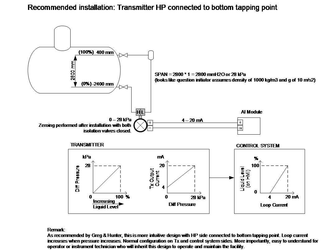
With modern transmitters such as Rosemount 3051S, you certainly have no negative pressure limitation issue. You have no problem connecting the HP side to the bottom tapping point. It is common to have upper range value (URV) and lower range value (LRV) at negative pressure for wet leg installation due to a typically higher density liquid in the wet leg.
I hope the following illustrations help convince your colleague not to go backward by opting for installation that requires signal reversal. Performing even a simple task such as calibration could potentially be confusing for the technician, especially when we don’t usually carry loop drawings and instrument datasheets to the field.