The following discussion is part of an occasional series, "Ask the Automation Pros," authored by Greg McMillan, industry consultant, author of numerous process control books, and 2010 ISA Life Achievement Award recipient. Program administrators will collect submitted questions and solicits responses from automation professionals. Past Q&A videos are available on the ISA YouTube channel. View the playlist here. You can read all posts from this series here.
Looking for additional career guidance, or to offer support to those new to automation? Sign up for the ISA Mentor Program.
Efrain Quinteros Peralta’s Question
I recently commissioned FOUNDATION Fieldbus instruments connected to a distributed control system (DCS). I would like to know how to perform advanced diagnostics on FOUNDATION Fieldbus networks and how to become an expert in FOUNDATION Fieldbus protocol.
Mark Nixon’s Answer
For an overview of FOUNDATION Fieldbus, I recommend the Process/Industrial Instruments and Controls Handbook, Sixth Edition. The next few paragraphs have been mostly extracted from this book.
FOUNDATION Fieldbus is an all-digital, serial, two-way communication system introduced in 1996. Two related implementations of FOUNDATION Fieldbus include H1 and high-speed Ethernet (HSE). H1 operates over 31.25 kbit/s and is generally used to connect “field” equipment such as sensors, actuators, and IO to host systems such as DCS systems and programmable logic controller (PLC)-based systems. HSE operates over 100/1000 Mbit/s Ethernet and is much less.
FOUNDATION Fieldbus supports multiple variables from each device. FOUNDATION Fieldbus also supports asset management and control applications. Asset management includes configuration, calibration, and diagnostics. Control includes both the definition of standardized function blocks, such as analog input (AI), proportional–integral–derivative (PID), and analog output (AO), and scheduling functions. The FOUNDATION Fieldbus H1 technology consists of a physical layer, a communication stack, and a user layer. The physical layer includes mechanisms to transmit and receive signals across the network. An H1 segment can support up to 32 devices. The number of devices per segment is usually less than this due to a combination of the number of devices supported by the host, total cable distances, and process cycle times.
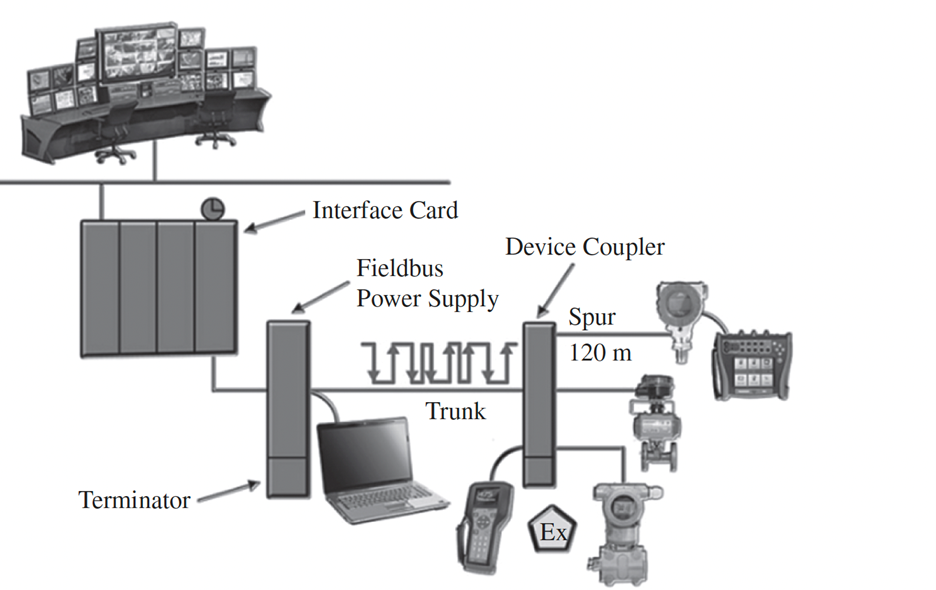
A typical fieldbus segment, as shown in the Figure below, consists of the following components:
- H1 card or fieldbus interface card: It is common practice to have redundant H1 cards, but ultimately this is application specific.
- Fieldbus power supply and signal conditioner: Integrated power supplies and conditioners have become the standard. These can be redundant or simplex.
- Terminators: Exactly two terminators are used per fieldbus segment—one at the power supply and one at the farthest point of a segment at the device coupler.
- Device couplers: These devices isolate any failed devices from the rest of the segment. Device couplers are optional but are often installed when there is concern for water egress into a conduit or when the instruments on a segment are critical to the process and the loss of an entire segment would create significant production ramifications.
H1 physical layer terminology
Troubleshooting depends a lot on which stage the plant is in (i.e., during commissioning or after some time of normal operation). Most problems with Fieldbus are installation-related, such as:
- Shield grounded in more than one point when the points were at different potentials.
- Water in field devices or junction boxes terminals.
- Bad or loose connections.
- Bad (i.e., bad design) ancillary devices such as terminators, power conditioners, intrinsically safe barriers, surge protectors, etc. After some time in the field or when ambient temperatures change, they often malfunction.
- Communication cables running too close to power cables or other interference sources.
- Variable-frequency drives (VFDs) without filters and proper shielding.
- Devices not properly grounded when the installation structure is noisy.
- During commissioning, you may find configuration errors that are relatively easy to find but issues related to network parameters, mainly when you have different suppliers for the system and devices. Some host systems use different settings for network parameters, causing big issues for those not aware of what may be happening.
DCS typically provide integrated tools for diagnosing and troubleshooting issues. For example, in DeltaV, there are diagnostics for port communications, as summarized below:
- Retries: Total Dll Retries is the total number of data link packets that the H1 card had to retry. If this statistic is steadily increasing, check the communication statistics for each device to see which device is causing the problem. The number of retries to a fieldbus device generally should be much less then 1% of the total requests sent to the device. If this is not the case, either the device is bad or there is a segment problem.
- Invalid responses: Total Invalid Responses is the total number of fieldbus requests that failed due to a fieldbus device returning an error. If this statistic is steadily increasing, check the communication statistics for each device to see which device is causing the problem.
- Stack errors: Total Local Stack Errors is the total number of fieldbus request that failed because the local communication stack returned a response that indicated an error. The H1 card might need to be replaced if this statistic is steadily increasing. Total Stack Rejected Request is the total number of fieldbus requests that failed because the local communication stack did not accept the request. The H1 card might need to be replaced if this statistic is steadily increasing.
- Timeouts: Total Request Timeout is the total number of fieldbus request that failed because the fieldbus device did not return a response. If this statistic is steadily increasing, check the communication statistics for each device to see which device is causing the problem.
Each manufacturer has their own diagnostics and troubleshooting information, so consult the manufacturing documentation for more details. There is also a lot of information in the FieldComm Fieldbus FOUNDATION System Engineering Guidelines document, and Fieldbuses for Process Control: Engineering, Operation, and Maintenance.
Luis Navas’s Answer
I’ll start with the second part of your question then proceed to the first part. To become an expert in any field implies studying, reading, and learning from experts; discussing and talking with others about the subject; living a very broad variety of practical experiences; and obtaining the maturity to strengthen and maintain all that knowledge. Now, talking about how to become an expert in FOUNDATION Fieldbus protocol, this is my suggested step by step:
- Theoretical steps:
- Read, study, and understand the documentation provided and referenced by your DCS manufacturer.
- Read, study, and understand the Fieldbus’ System Engineering Guidelines, whitepapers, and referenced documentation provided and mentioned by the FieldComm Group.
- Look for all key manufacturers of FOUNDATION Fieldbus and their product portfolios, datasheets, manuals, and capabilities.
- Design steps:
- Use any software package to design FOUNDATION Fieldbus segments (there are several available).
- While using the software, try to use different kinds of cables, segment protectors, power supplies, and instruments. Make topologies errors, check the restrictions, and test it as much as you can.
- Try to design an intrinsically safe segment (i.e., FISCO).
- Participate in a real engineering design.
- Practical steps:
- Do the configuration in the DCS.
- Participate in a factory acceptance test (FAT).
- Participate in a site acceptance test (SAT).
- Participate in the segment installation checklist validation (proper wiring, grounding, peak to peak voltage, waveform, and general installation).
- Participate in the commissioning of the process instruments.
- Participate in the startup.
- Perform a FOUNDATION Fieldbus instrument replacement.
- Perform diagnostics and maintenance.
When you pass through these steps, you will gain more expertise. To answer the first part of your question about diagnostics, there are several ways to diagnose a FOUNDATION Fieldbus segment:
- Visual inspection.
- Grounding/shield measurement.
- Peak to peak voltage measurement and waveform checking (a portable scope is needed).
- Using the diagnostic capabilities available in your DCS (as a reference, you can check the Control Global article, A structured approach to control system diagnostics).
- Use more sophisticated tools as a FOUNDATION Fieldbus tester/monitor, use handhelds or the use of a dedicated diagnostic module since its part of the segment design (here, it is important to know what the market offers, as mentioned earlier).
Greg McMillan’s Answer
To provide more guidance, here is another excerpt from the Process/Industrial Instruments and Controls Handbook, Sixth Edition.
Utilizing FOUNDATION Fieldbus Devices to Meet Application Requirements
In a fieldbus environment, the user application is defined through the configuration of function blocks. This approach is similar to the configuration of control and monitoring in a DCS today. However, the fieldbus function blocks support applications that involve measurement and control and can be distributed between fieldbus devices. Such capability allows the base-level process control and measurement done today in DCSs and single-loop digital controllers to be implemented in a fieldbus device.
Monitoring, calculation, and control functions may be defined by configuring function blocks within a fieldbus device and configuring the connections between function block input and output parameters. Both fieldbus valves and transmitters support control and calculations. In addition, auxiliary measurements such as stem position or limit switch status for an on–off valve are often available through fieldbus.
The function block application in FOUNDATION fieldbus devices enables control, measurement, and calculation functions to be distributed between field devices. For example, a flow measurement might be implemented in a transmitter using the analog input block (AI block). This transmitter publishes its measurement value and its status. A valve on the fieldbus segment can support a control block (PID block), which subscribes to the published measurement value. Based on this value and its target setpoint, the PID block can calculate an output required to maintain the setpoint. Within the valve, this output might be fed to an output block (AO block) to adjust the valve.
To successfully distribute control between fieldbus devices without degrading control by communication delay, the scheduling of function block execution and related communications is critical. Thus, scheduling communications in conjunction with function block execution is an integral part of the FOUNDATION fieldbus specification.
Function blocks and tools used for process analysis, such as trending of measurement versus time, often assume periodic sampled values. In such cases, it may not be practical to compensate for variation or jitter in the sample time. Thus, fieldbus enables measurements to be sampled on a precisely periodic basis, independent of fieldbus communications. Through the scheduling of block execution, these sampled values may be made available to control blocks with minimal delay. Thus, with proper scheduling, it should be possible to ensure that the total dead time from execution (one half the largest sample time plus latency) will be less than 10 percent of the total loop dead time and will have a negligible effect on performance for critical loops.
The low processing power of intrinsically safe devices, combined with the distribution of control between fieldbus devices, imposes some constraints on the design of fieldbus devices. To support the periodic sampling of inputs, a common sense of time is maintained in each device on a fieldbus segment. Each device maintains a schedule that determines which blocks within the device are to be executed. Based on this, it is possible to schedule communication of block output values between devices for calculations and control.
To obtain an accurate measurement, a device may sample a process measurement at a much faster rate than is needed for control or monitoring requirements. For example, a measurement may be processed 20 times/s, even though it may be used in control only 5 times/s. A transducer block is defined in fieldbus devices to contain the parameters associated with the basic measurement. The processing of the transducer block is defined to be independent of function blocks that reference the transducer block. To accommodate these differences in execution rates, software filtering is provided in transducer blocks. Through this filter, the frequency content of the measurement may be matched to the function block execution rate. As part of input block processing, checks on associated hardware and software are performed. In addition, process alarm detection may be enabled. On the detection of a change in block status or process alarm condition, an event notification is generated. This notification includes the time of detection and a sub status that gives further information on the alarm or event.
One final note on configuring fieldbus blocks. Some PID tuning settings may be different and options (e.g., dynamic reset limit) may not be available on some implementations of PID blocks. Tuning applications, such as relay oscillation tuning techniques, should work well even when PID blocks are in the field.
FOUNDATION Fieldbus Best Practices
- Limit the number of fieldbus devices on a single fieldbus segment to 16. This helps ensure reasonable update rates of dynamic fieldbus parameters in the host interface.
- On a single fieldbus segment, install no more than 12 fieldbus devices that are powered by the segment. For an intrinsically safe installation, limit the maximum to four to six devices based on individual device power consumption.
- Locate fieldbus devices on a single segment if control or calculations are distributed between these fieldbus devices.
- Use a maximum of 16 function block input and output links between fieldbus devices on a single segment to provide reasonable loop execution rates and display update time at a host.
- Purchase fieldbus devices that have been certified by the Fieldbus FOUNDATION to be interoperable. Consider the function blocks and diagnostics supported by the fieldbus device when selecting a fieldbus device.