The following discussion is part of an occasional series, "Ask the Automation Pros," authored by Greg McMillan, industry consultant, author of numerous process control books, and 2010 ISA Life Achievement Award recipient. Program administrators will collect submitted questions and solicits responses from automation professionals. Past Q&A videos are available on the ISA YouTube channel. View the playlist here. You can read all posts from this series here.
Looking for additional career guidance, or to offer support to those new to automation? Sign up for the ISA Mentor Program.
See Part 1 here. See Part 3 here. See Part 4 here. See Part 5 here.
Greg McMillan’s Question
What are the biggest mistakes you have seen in automation system design, configuration, calibration, installation, checkout, commissioning, and maintenance? What were the consequences and the fixes and what can be done to prevent future occurrences?
Greg Breitzke’s Answer
As a maintenance and reliability professional that spends a significant amount of time reviewing scope development through detailed engineering, I think sometimes we focus too much on the bells and whistles associated with advanced control and diagnostics while missing fundamentals. We need to shift the “high value engineering” mindset where we just look at the installation costs and compare it against the total cost of ownership (TCO). I understand there are competing priorities as the project teams are constantly being indexed against cost and schedule, but how much is saved when the maintenance costs can be increased exponentially?
Consider the following example: A differential pressure transmitter with process diaphragm is being used to measure level in a tank with a 120,000lb storage capacity of an extremely caustic material. Installing a double block and bleed allows for in-situ maintenance, but direct mounting saves the project money. This $1,500 installation savings now requires a little more pre-work for maintenance/calibration:
- Full system engineered lock out plan requiring engineering and operations support
- Full product de-inventory
- Internal vessel heel removal and decontamination
Preventive maintenance (PM) to verify the calibration now requires:
- Hazardous line breaks
- Disconnecting the instrument mechanically and electrically
- Transporting transmitter to the shop
- Decontaminating
- Connecting mechanically and electrically for calibration check
- Verifying calibration
- Disconnecting mechanically and electrically
- Returning to the unit
- Installing mechanically and electrically, and loop checking to confirm it wasn’t damaged with unnecessary handling
- Finally, turning it back over to the unit to put the tank back in service.
How much did that $1,500 installation savings really save? While this seems to be an extreme example, it happens every day in facilities that may not yet have site standards promoting good engineering practices and reliance on minimum code requirements. We need to look past the installation and minimum code requirements to promote good engineering practices that deliver a lower TCO for the client.
Direct cost savings:
- Decreased labor costs
- Grade or platform accessibility eliminates unnecessary work from ladders or costs associated with scaffold
- Direct vs. remote mounting options for operator and maintenance visibility
- Installation of bypasses and double block and bleeds that allow for in-situ maintenance to decrease operational downtime
Indirect cost savings (and personnel safety):
- Installation of bypasses and double block and bleeds that allow for in-situ maintenance to reduce potential personnel exposure
- Installation of individual power/signal isolation, preventing multiple devices from being offline or forcing additional technician personal protective equipment (PPE) requirements to work on “live” equipment.
- Employees feel valued and safe and are more productive and less likely to seek other opportunities.
In conclusion, I suggest making an increased effort to design for maintenance. It can be the best “high value” effort we offer to our customers by reducing revolving costs over the equipment or system life cycle while increasing efficiency and safety. Isn’t that the end goal for automation?
Mike Laspisa’s Answer
Here are a few:
- Incorrect control valve sizing primarily related to blindly accepting the sizing Delta P from the process engineer without an independent evaluation of the dynamic pipe run or even the actual physical location of the valve in the line.
- In the early days of interfacing variable frequency drives (VFD) with distributed control system (DCS) control, the drive and DCS non-isolated analog output (AO) card literature implied that a current isolator would be required for the 4-20mA speed setpoint signal. Without discussing the approach with either the drive manufacturer or DCS engineer, $15,000 was spent on current isolators. It turned out that the isolators interfered with the drive control and were not required in the first place.
- On a large coal boiler, a programmable logic controller (PLC) and DCS graphic user interface (GUI) were used to control the 24 baghouse/air heater drop valves and pneumatic transport system. However, the PLC software and DCS graphic did not allow the operator to take a drop valve out of service for maintenance, hold the sequence longer than the cycle timer allowed, or transfer the sequence to another drop valve cluster if a sub-header had an isolation valve problem. In most process sequential control programming/configuration/GUI designs, the often-overlooked issues relate to the operator’s ability to easily recover from device failures and to isolate them for maintenance, as well as provide a means to hold, transfer, or retry the sequence from a safe step after a malfunction.
Hector Henry Torres’s Answer
After mechanical completion, enough time must be given to execute a point-to-point checkout. This is to make sure all instrumentation, sensors, and final control elements are properly wired from the field to the control system. As the startup date is getting close, each discipline gets into a fast-track mode that makes it easy for the people to fall in mistakes. Most common are loose bolts or loosening of wires at the terminal blocks, connections at the wrong channel, and/or wires at the wrong terminal of the input/output module.
A very good practice after checkout is to perform what is sometimes called “water batching.” This, in essence, refers to testing a given piece of the process which will be run for some time at a low rate or for some batches to determine if all performs as intended. This helps the team to identify early issues. I have seen how water batching can reveal design and construction mistakes:
- Wrong valve action, wrong controller action, and wrong split control action leading to control issues in temperature control
- Poor feed stability or accuracy from not properly isolating feeders due to tight socks or wrong length based on how the pipes line up
- Flow meters far away from the process, resulting in unbalances in raw materials’ ratios that lead to precarious startups and quality issues
- Wrong gear box ratios or wrong roll diameters entered when configuring variable speed drives that lead to differences in linear speeds. This is especially bad if this is a sheet line were all rolls need to run at a coordinated speed. The control system sees all rolls turning at the required speed while in the field, and some might not. This leads to film over stretching, slippage, and even sheet wandering.
Peter Morgan’s Answer
The omission of factory acceptance testing of implemented control strategies based on functional requirements can add to commissioning delays and in some cases production loss and impact on safety integrity. Essential to the execution of the factory acceptance test is a detailed written procedure with expected behavior described. The control narrative and functional logic diagrams should be used as reference documents for the tests and form and, together with the procedure and recorded results, the record of compliance with the design intent.
In the implementation (configuration) of complex control strategies, even with the best intent, errors can occur in the selection of configurable options at the function block level that affect behavior. Issues with controller initialization, for example in ganged or split range control and timing issues in Boolean logic, if not discovered during testing can be a challenge to resolve during commissioning. Functional testing also provides the opportunity to verify the design of the operator interface, and with the participation of a control room operator, can provide the opportunity for refinement and early acceptance of the operator interface.
For complex loops, a simple process model can provide the feedback to the controllers to reduce the time required to carry out functional testing. Since in contemporary digital control systems the suite of functions provided for process control can be readily used to build simplified process models, feedback can be added with surprisingly little effort. Some DCS vendors may go further in providing virtual input channels which minimizes any temporary adjustment of the configuration to allow the use of simulated process measurements.
To sum up, a well-executed and documented factory acceptance test, in addition to the aforementioned benefits, will be appreciated by any who come under the pressure that typically accompanies the commissioning, on-line testing, and tuning of the control system.
Damien Hurley’s Answer
One of the largest mistakes I’ve seen stems from a lack of awareness of the ASME B16.5 material rating tables and the subsequent impact on the piping/instrument interface flange. I have heard several stories about significant re-work being required when an instrument has been bought with a flange that isn’t compatible with its piping isolation valve. In the instance below, I’ve shown an example where a 600# piping flange has been specified against a 900# instrument.
Within B16.5 common metals used in the industry are arranged into formal groups with tables specifying working pressures of that particular group by pipe class (150#,300#,600#, etc.). Each table extends to 538°C (approx. 1,000°F) and from the various tables, it's evident that the working pressure of all groups derate as the temperature is increased. An important point to note is that the factor by which a group’s working pressure derates differs across the material groups and therein lies the potential for error.
A common material of construction for main piping is carbon steel (A105) which is a group 1.1 material. I’ve shown the PT derating curve for group 1.1 below, with a fictional P&T design of 65 bar(g) & 300°C. A piping engineer will provide a 600# flange as standard in this service, in-line with the pipe class. 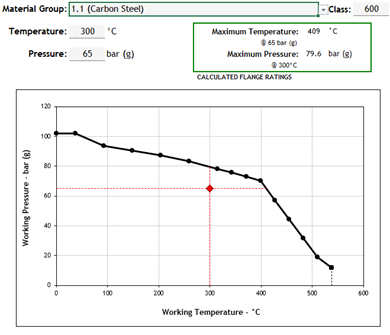
The most common material for all things instrumentation is stainless steel (316SS), which is a group 2.2 material. The derating curve is shown below for group 2.2, at the same P&T design as above.
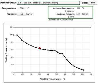 In the above instance, the same design pressures and temperatures used in the group 1.1 case above now exceed the flange ratings for group 2.2 materials in 600#. This instrument will need to be uprated to comply with B16.5. I’ve assumed that the next available class would be 900#.
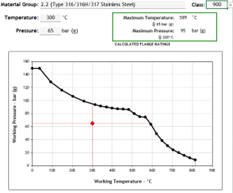 It is imperative that the instrument engineer relay the 900# flange requirement to the piping team as soon as possible. In a perfect world, this increased flange rating would be flagged by the instrument discipline well before any instrument material requisitions are issued as it can be observed from some time spent analyzing the piping line list. Should the above issue fall by the wayside during the design stage, it will require significant rework to rectify these errors (of which there can be a significant number) once the error eventually comes to light during construction.
In essence, this design mistake is a communications issue, but given the ramifications to rectify the installation at site, it can be one of the most problematic. Regardless of the potential for re-work and re-design, the derating of materials at elevated temperatures is something that all instrument engineers should be aware of as it can present significant safety concerns at elevated temperatures. This problem can be overcome early in the design stages of a project, but like the vast majority of engineering mistakes, poor communication and “siloed” working lies at the root cause of the problem.
Mohd Zafran Hamid’s Answer
To my limited experience, I have seen quite frequently these two errors:
1. Lack of operator friendliness for the setting of reverse/direct at control loop components when involving a failed open (FO) (air to close) control valve.
Though the settings can be correct (achieving the final negative feedback control loop), it is not necessarily intuitive. For an intuitive display to the operator in control room, the controller output (CO) signal command to the control valve should align with valve position—0% and 100% CO represent a shut and fully open valve position, respectively.
For control loop with FO valve, we usually see the opposite, whereby the controller is configured in such a way that it’s CO indication on human-machine interface (HMI)/DCS graphics is not aligned with valve position. For example, 20% CO means commanding the valve to be 80% open. In the event that intervention by an operator is required, when the valve is demanded to be fully closed, the operator may fully open the valve if he accidentally keys in a CO of 0%.
There are many great guidelines written on how to correctly configure the controller actions, such as Appendix C Checklist for PID Controller Features from 101 Tips for a Successful Automation Career, Table 1 of Good Tuning: A Pocket Guide Fourth Edition, and others (I would also use simple guides from Harold Wade). For a negative feedback control loop to work, there must be an odd number of sign reversals around the loop. Let’s use flow control loop using a FO (air to close) valve as an example.
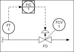 Figure 1
The flow process is naturally direct. To achieve negative feedback control, the loop may be configured as per Figure 2. As we have one sign reversal (odd number), the loop will work. With only the valve element reversed (increase-close), the rest of the loop components can be set as direct. This setup, however, is not so intuitive for the operators.
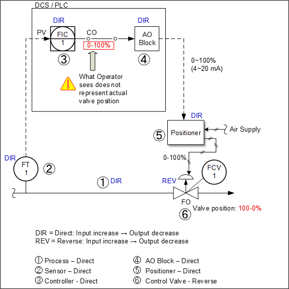 Figure 2
For an operator-friendly approach, the loop can be configured with additional sign reversal in the controller and AO block. Finally, we have three sign reversals which still works as we have an odd number. Better yet, our CO now aligns with valve position (see Figure 3). Note that instead of an AO block, reversal setting can also be done at the positioner. However, this is not advisable as this setting could potentially be lost when someone else replaces/upgrades the positioner later.
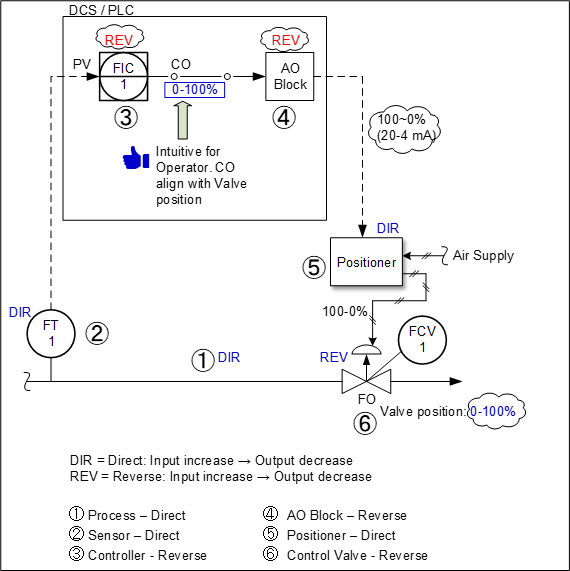 Figure 3
2. Wrong configuration of override control scheme
Instead of using normal high/low selectors on the output of controllers, some DCS configurators misunderstand by configuring unnecessary conditional logic which doesn’t work. Figure 4 is the wrong implementation that I have seen for override control. Most of the time, the selector switch is being forced manually by the operator at one selected position only.
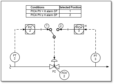 Figure 4
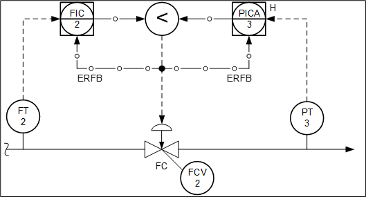
This mistake could be due to a lack of understanding on how override control works. Figure 5 is showing the correct implementation.
![]() Figure 5
Figure 5