Part I
The driver behind digitalization is the growing demand for accuracy, enhanced quality, and reliability. The market dynamics have compelled the manufacturing industry to bring in new products, modified designs to match changing consumer sentiments, customizations, and faster deliveries. Robots have been the friends of the manufacturing industry for decades now, and so has "machine vision," per se.
Robotics and machine vision have independently reached stability and technological maturity. Recent developments have been rather complementary to each other in making processes more efficient. This article will elucidate some insights about vision-guided robotics (VGR) in the manufacturing segment. Though VGR is equally relevant for other robot types such as mobile robots, humanoids, Cartesian, and SCARA robots, we shall focus on the applications and challenges of articulated robots.
Before we go deep into our core topic, it is important to understand some important concepts of machine vision and industrial robots.
Machine vision can be defined as the atomization of human seeing. It needs not only to capture an image (the function of our eyes), but also to process these images and generate results (the function of the brain). Machine vision systems rely on digital sensors protected inside industrial cameras with specialized optics to acquire images, so that computer hardware and software can process, analyze, and measure various characteristics for decision making.
Typical machine vision applications can be broadly categorized into four types, namely:
- Guidance
- Identification
- Gauging
- Inspection
While tasks like identification, gauging, and inspection systems have their own purposes where robots add value to the application, our focus in this article is on robot guidance. Machine vision (MV) systems can locate a part and ensure that it is placed correctly in a particular assembly. MV systems can also help identify the location of a component in 2D or 3D space, and help robots precisely track the coordinates of this component. MV systems reduce the complexity of having fixtures required for this purpose. To understand this, we need to first look into how a robot positions itself to locate the component.
A robot coordinate system comprises of different frames of references. The main coordinate systems used to describe the motion of a robot are shown below in Figure 1.1. The control of the gripper or the tool is most important and its position is achieved through coordinated motions of one or all robot axes. Because different types of grippers and tools have different dimensions, a special point called the tool centerpoint (TCP) is selected, independent of the tool type. This point is the origin point of the tool coordinate system. A similar point can be used to describe the gripper or the wrist coordinate system. The mutual connections of a tool, a wrist, and other coordinate systems are shown in Figure 1.2.
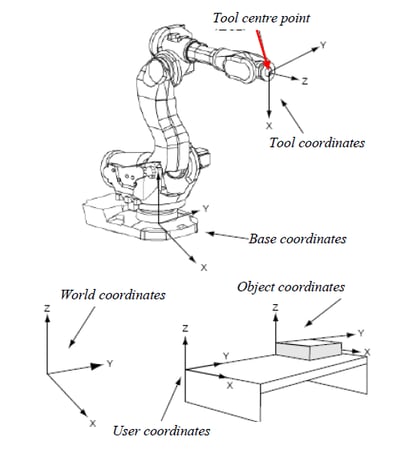
Figure 1.1
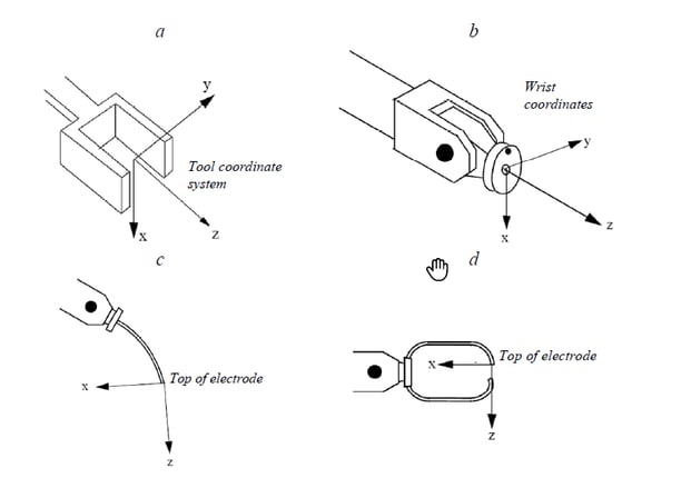
Figure 1.2
Images: ABB Robotics
The TCP bears relation with the wrist coordinate, base coordinate, world coordinate, and the object coordinate systems. Ideally, it is expected that the object’s coordinates match precisely with the set coordinates of the TCP—meaning that the origin point of the object is taught to the robot via programming and the TCP coordinates are recorded. Therefore, to achieve repeated accuracy, the robot and the object have to come at the same point every time.
The robot positioning is governed by servo mechanisms, and therefore is pretty accurate. In case of fixed located components, their positioning accuracy is dependent upon a number of factors such as machining tolerances, locating fixture tolerances, and indexer table positioning accuracy and repeatability. Therefore, the TCP of the robot may not match with the actual coordinates of the object due to the offset between its desired and actual coordinates, and there will be a positioning error. If the robot is expected to pick up the object or perform any operation on it while the object comes randomly positioned over a conveyor, then determining its origin becomes next to impossible if there is no system like machine vision to guide it.
If deployed, machine vision systems can identify the object’s real-time coordinates and feed them to the robot, which then compensates the offset into the TCP. Thus the tool positioning accuracy is ensured. This method is mostly used for applications such as welding and glue dispensing, for fixture components, and for robotic "pick and place" of randomly distributed objects on a moving conveyor. The above examples hold good for objects having positioning inaccuracies along the 2D plane, so a 2D machine vision system would be used.
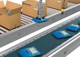
High-speed robotic "pick and place" of objects using 2D vision guidance. Image: Cognex Corporation
For applications such as robotic bin picking, where the robot is expected to pick up objects kept randomly in a bin, 3D spatial analysis becomes necessary. Here, not only are the X, Y, and Z coordinates important, but the orientation angles along all three axes are crucial for the robot to identify the easiest object to pick without any collisions. It is obvious that 3D machine vision systems are deployed in this setting.
The most popular 3D machine vision system is a setup using stereo vision with two cameras providing coordinates and the height map. The crucial task here is camera calibration and the machine vision algorithm that will combine images from both cameras and build a 3D image. An image of the bin is analyzed to derive the TCP coordinates of the most easy component to pick. Some other 3D techniques are laser triangulation and time of flight.
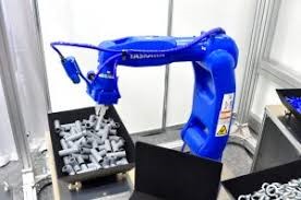 Robotic bin picking using 3D vision guidance. Image: Yaskawa Robotics
Part II
Image Acquisition
A good-quality image is the key for successful VGR. The three main components here are the camera, optics, and the illumination.
Camera: There are some important things to be considered during the selection of cameras for robotic applications. Although commercial cameras in the market do acquire images, the industrial environments where these systems are deployed can be really challenging. Here, the cameras are exposed to harsh environments and are expected to deliver consistent good-quality images every time for hundreds of thousands of cycles. Add to that the shocks and vibrations incurred due to robot movements and the overall equipment vibrations.
The communication interfaces need to be robust, sustaining in these tough conditions so that there are no interruptions in communications during the operation. Ethernet-based protocols offer good reliability and longer cable lengths necessary for this application. Ingress Protection compliance becomes crucial especially if the system is deployed in a dusty environment. PoE is a preferable power source to avoid multiple cables. The camera cables are subjected to a lot of cyclic bending through cable trays and harnesses on the robot arm, so drag-chain compliant cables should be used.
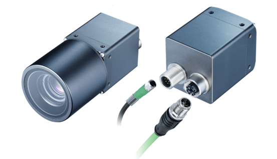 Image: Baumer
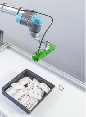 Image: Pickit 3D
The resolution of the camera has to be calculated considering the overall field of view (FOV) and the positioning accuracy desired.
Optics: Suitable optics depending upon the FOV, working distance (WD), and the camera sensor size must be selected. The two most important factors to be considered are:
- The barrel distortion should be kept to the minimum possible, and
- The robustness of the lens, as it is subjected to the same amount of shocks and vibrations as the camera; crucial lens settings such as the iris and focus can be affected if left unaddressed
Illumination: Illumination of the object plays a crucial role in VGR. The lighting should be such that it highlights the feature to be inspected in the component. The component or the contour that is programmed has to be precisely identified within the desired accuracy of the system. Therefore, based upon the object and the contour, suitable illumination has to be selected. Whereas the component picking or welding/glue dispensing type of applications mostly require simple diffused bar lights, the robotic bin picking applications using stereo cameras often make use of structured pattern lights projected on the component to gather contours and derive profiles.
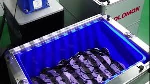
Structured lighting used in 3D bin picking. Image: Solomon 3D
Challenges in Robotics with Machine Vision
In a standard 2D robotic machine vision application, there are several challenges which need to be addressed:
- Distortions
- Coordinates calibration
- Z calibration
- Coordinate alignment
Distortions: There are two main types of distortions that occur and need to be corrected before the vision system is ready for the VGR.
- Lens Distortions: Lenses (especially the wide-angle ones) cause distortions in the acquired image. This is known as “barrel distortion.”
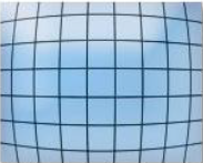
Barrel distortion. Image: Baumer
- Distortions caused by inclined mounting of camera
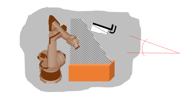 Image: Baumer
Robots require clearance to operate, so cameras often need to be mounted at an inclined position. This causes distortion in the image acquired.
Both of these types of distortions need correction and calibration so that the coordinates acquired are accurate.
Coordinates Calibration: Robots work on coordinate systems defined in units like millimeters or inches, whereas cameras work on pixel counts. Therefore, it is required to calibrate the camera so that the system understands the correlation between pixels and the units of the coordinate systems.
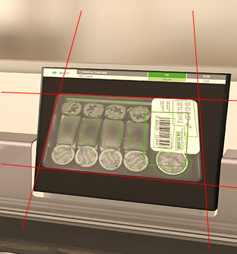 Image: Baumer
It is important that the measurement happens at the same working distance (distance between the camera and the object) every time. Since robots work in 3D, "gripping" also requires a "Z" specification.
Z Calibration: Z calibration is used to calculate X- and Y-coordinates if the Z-axis varies within the depth of field* of the lens. The camera is calibrated using a specific procedure with the calibration plate (discussed later).
Coordinate Alignment: The robot and vision system have their own coordinate systems. Their deviations are:
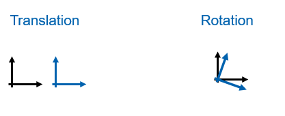
To overcome this problem, calibration is carried out. The robot knows its own position and also the position of the TCP, whereas the vision system is calibrated on a calibration plate. The robot calculates the offsets, and alignment is carried out.
This is a very important step. The robot must follow the path that starts from the origin point defined by the vision system. If not executed properly, incorrect calibration can cause serious path deviations and may result in collisions.
Calibration plate: The vision system calibration is carried out using a standard calibration plate that has markings with precise dimensions. Figure 2.1 shows some examples of calibration plates.
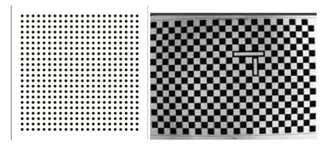
Figure 2.1
Correcting lens and mounting distortion using calibration plate: The calibration plate is placed at a certain distance below the camera and the image is acquired, as shown in Figure 2.2.
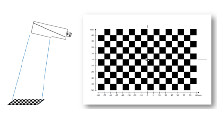
Figure 2.2: Camera positioning
Image: Baumer
Once the distortion calibration is carried out, the image looks aligned. This is shown below in Figure 2.3.
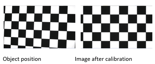
Figure 2.3
Coordinates calibration using calibration plate: The grid lines or markings on the calibration plate are related to the number of pixels covered in the camera. It is important to position the location pointer precisely on the calibration plate.
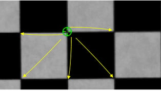
The pointers are placed on the points/corners of the plate. The distances between these points are known, and are then entered into the calibration parametrization fields of the software. The vision system then calculates the number of pixels consumed to measure that distance. This setting holds good as long as the working distance, FOV, and camera mountings are maintained. The system needs to be re-calibrated if any of the three things change.
Trends and Advancements
VGR is not a new technology. It has already developed and become quite a mature application. Almost all the robot manufacturers now offer integrated solutions for VGR. However, the latest advancements in camera technologies (such as high-speed cameras, 3D time of flight cameras, and integrated stereo cameras) and in software technologies (such as artificial intelligence and machine learning) have added that extra piece of reliability and robustness to the whole application.
Deep neural networks are deployed to teach and reteach different possibilities of component positioning and orientations along all planes. The many possibilities to be learned can lengthen the networks' training time, but the latest computing devices (such as GPU) make tasks less time consuming. Cloud-based platforms for machine learning are also currently being deployed.
Conclusion
VGR is gaining rapid popularity across all domains in industry. The application once largely driven by the automotive segment now finds other takers like food and pharmaceuticals for high-speed robotic pick and place, palletizing and de-palletizing, heavy engineering for seam tracking of welding robot, glue dispensing, and so on. There is a need to set up standards to ensure inter-compatibility among the vision system manufacturers and robot builders. As the world looks towards the “new normal” in manufacturing, VGR definitely has a major role to play.
This article originally appeared in the summer 2020 edition of the International Society of Automation (ISA) Automatic Controls and Robotics Division (ACARD) newsletter. It is republished here with the permission of its author.
Interested in reading more articles like this? Subscribe to ISA Interchange and receive weekly emails with links to our latest interviews, news, thought leadership, tips, and more from the automation industry.