

This post was authored by Mohammad Al-Khalifah, of Saudi Basic Industry Corporation, and Greg McMillan, industry consultant, author of numerous process control books, 2010 ISA Life Achievement Award recipient and retired Senior Fellow from Solutia Inc. (now Eastman Chemical).
There is a high potential to reduce pumping-energy-consumption cost through properly designing and selecting the pumping system and controls. Electrical motor-driven pump systems account for nearly 20 percent of the world energy use and 25-50 percent of the total electrical energy use in certain industrial facilities.
Pump energy consumption is often one of the larger cost elements and may dominate pump lifecycle cost, especially if pumps run more than 2,000 hours per year. Pumping applications with a variable-flow requirement typically use a throttling valve, recirculation line, or a variable-motor speed to deliver the desired process flow rate. Flow control by valve throttling wastes energy by diverting excess flow through a bypass or by restricting the pump discharge. Additionally, valves can be a source of emissions and suffer from corrosion, erosion, plugging, sticking, cavitation, and leakage.
The most efficient mean of flow manipulation is pump-speed adjustment. Since per the "affinity law" brake horsepower varies with the cube of centrifugal pump speed, reducing pump speed reduces pressure imparted to the fluid and in return reduces centrifugal power consumption. In addition to energy conservation, there are also a number of operational benefits, such as improved reliability, process performance, reduced life-cycle cost, and decreased fugitive emissions by eliminating the control valve and the associated piping.
Background
An electric motor-driven centrifugal pump is a process device that consists of a set of rotating vanes (impeller or rotor) enclosed within a casing that continuously imparts kinetic energy to a fluid. The head developed by the pump is entirely the result of the velocity imparted to the pump fluid by the impeller. The pressure increase across the pump is the result of converting the velocity head to pressure in the pump casing.
Selecting centrifugal pumps for an application requires evaluating pump performance characteristics against the process requirement or system curve. Pump characteristics are typically delivered by pump manufacturers in a graphical format called characteristic curves. These curves provide information about pump performance in terms of total dynamic head, brake horsepower, net positive suction head required, and efficiency for the capacity range of the pump, as plotted in figure 1.
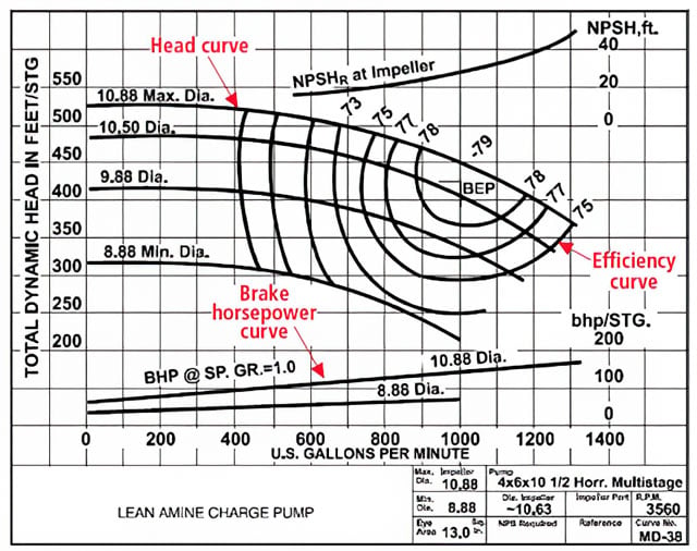 Figure 1. Centrifugal pump performance curve
Before proceeding to pump selection, the head-flow curve for the piping system that is being pumped into must be defined. This type of curve is called a system curve and typically represents the sum of the static head and the dynamic head that you need to pump against. The static head is a function of the elevation difference between the suction and the discharge or backpressure that the pump is operating against.
The dynamic head represents the friction losses from the fluid that results from the piping system. Plotting the pump curve and system curve will result in an intersection point, which is called the operating point. This point indicates the head and the capacity at which the pump operates in the system and gives the maximum flow required by the system, as illustrated in figure 2.
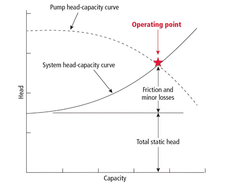 Figure 2. System curve
Most often this intersection point does not fulfill all the plant process requirements downstream of the pump. In some cases, the process requires varying flow rates and head conditions. Hence, some sort of control will need to be applied either in the pump discharge or in the pump prime mover.
The most common method of flow control is to throttle the flow on the discharge side of the pump. A more efficient option is to regulate pump flow by varying pump speed of the motor in the prime mover.
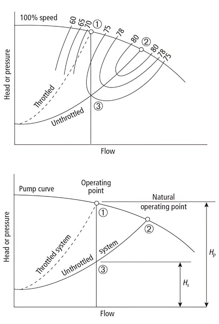 Figure 3. Control valve throttling and pump efficiency
Another method for constant-speed pump control with valves recirculates some of the discharge flow back to the pump suction pipe or other supply source, such as a tank. This type of control is also used to maintain some flow through a pump to avoid deadhead or cycling at a low flow from operating on the flattest part of the pump curve. Opening the recycle control valve rotates the system curve clockwise, which causes the modified curve to intersect further to the right on the pump curve at a higher flow rate and a lower pump head compared to the original operating point. A wide-open recycle valve will cause the pump to run at the end of the pump curve with a higher flow rate and lower pump head, which may lead to pump cavitation damage. Besides this concern, there are other drawbacks of using a control valve for pump control that are summarized below:
- Energy is wasted due to the pressure drop caused by the discharge valve and flow recycling.
- Stiction, backlash, and other mechanical issues are posed by the control valve. Control valves have a dead band varying between 0.1 percent and 10 percent and a resolution varying from 0.05 percent to 5 percent.
- Positioners have special tuning settings, but rules and procedures are not well documented.
- Reducers, flanges, air supply lines, and isolation valves are required.
- Control valves are in the maintenance shop more than any other control device.
- Fugitive emission is released from control-valve packing.
Flow control with a VSD
There is an everyday analogy that can help explain the efficiency advantage of a variable-speed drive (VSD). Imagine you are driving a car. If you are driving on a highway and entering a population area, speed must be reduced so that you do not risk your own and other lives. The best possible way to do that is to reduce motor-rotation speed by taking your foot off the gas pedal and, if necessary, changing to a lower gear. Another possibility would be to use the same gear, keeping your foot on the gas, and at the same time reducing speed simply by braking. This would not only cause wear in the engine and brakes, but also use a lot of fuel and reduce your overall control of the vehicle, which is the case for a "control valve."
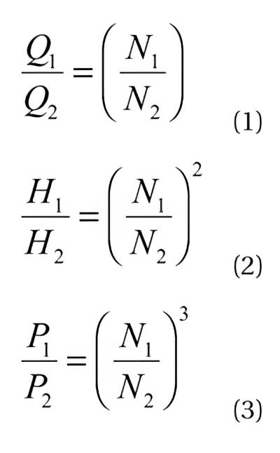
A VSD changes equipment speed to provide the torque-energy input needed to supply the hydraulic-energy output to the process. In this type of control system, the curve is not changed to match the required operating point, as previously discussed for control valves. Instead the pump speed is altered to move the pump performance curve in figure 1 upward and downward in accordance with affinity laws. These laws govern the relation between pump speed, head, and input power to the pump (brake horsepower). These laws (equations 1-3) are:
Where:
Q = pump discharge volume flow rate (gallons per minute)
N = pump speed (rotations per minute)
P = pump shaft input horsepower
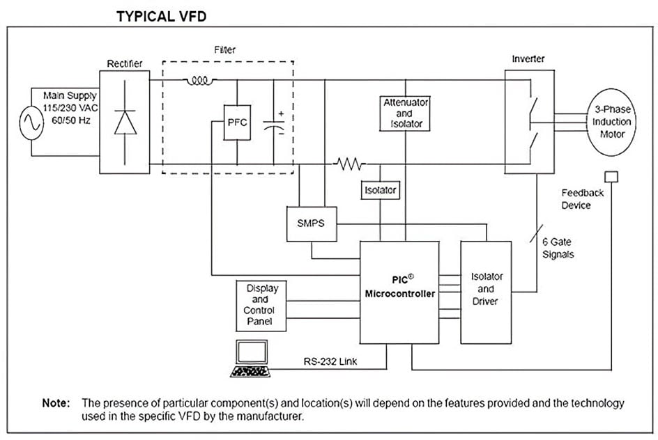 Figure 4. Typical variable frequency drive
There are several types of AC variable speed drives on the market. Two of them are pulse-width modulation (PWM) and variable-frequency drive (VFD). PWM is mainly used to vary voltage frequency or current to the pump motor. A PWM drive consists of a rectifier, inverter, operator interface, and other control and diagnostic microprocessors. AC line voltage is rectified and filtered to create a DC voltage. The DC voltage is then inverted to a variable frequency voltage where frequency is proportional to the drive input signal by PWM. The square wave output is then filtered to create a sine wave as depicted in figure 4. PWM introduces less noise and has a higher power factor and better low speed performance than older drive technologies.
Cases where a VSD is particularly advantageous
Extremely difficult and hazardous streams benefit from eliminating a throttling valve. The internal flow element and seating or sealing surfaces can be coated by sticky fluids, plugged or eroded by slurries and molten fluids, corroded by aggressive chemicals, and stuck from high temperatures. Cavitation from flashing in the vena contractor of a control valve can lead to excessive noise and cavitation damage. Highly viscous materials can result in operation in the transition region between turbulent and laminar flow. In these cases, using a VSD can reduce maintenance.
For pumping systems where the flow demand often drops, control valves will frequently be operating at lower throttle positions, wasting more energy by a greater pressure drop across the valve. Additionally, to achieve the required turndown, the percentage of system-pressure drop allocated to a control valve must be increased from the 5-20 percent normally stated to minimize energy costs. The energy savings are proportional to the cube of the speed; therefore, in these applications, the energy savings from using a VSD are considerable.
To make a more intelligent decision on the percentage of system pressure drop that should be allocated to the valve and thus the potential energy savings, equation 4 shows the effect on rangeability. The installed characteristic is a function of the valve-to-system pressure drop ratio (ΔPR) and the fractional flow coefficient (Cx) that depends upon the inherent flow characteristic. The minimum practical flow coefficient is set by the stick slip from the higher seat and seal friction as the valve approaches the closed position. A plot of the equation for a linear and equal percentage trim shows the installed characteristic becomes more "quick opening" and linear, respectively, as the pressure drop ratio decreases. For both trims, the flow characteristic bends over more at the top end of the stroke, and the flow at the low end of the stroke is higher as the pressure drop ratio decreases. The result is a decrease in rangeability.
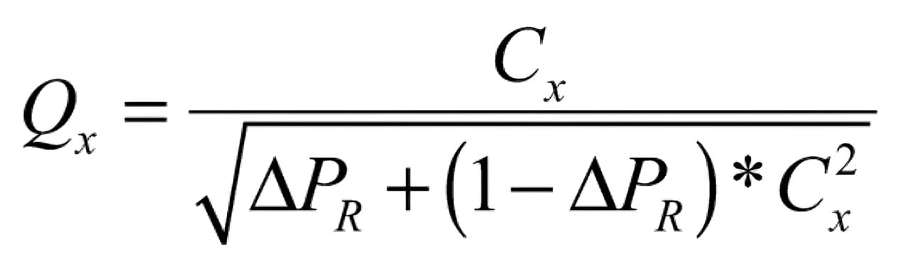
Where:
Cx = flow coefficient expressed as a fraction of maximum (dimensionless)
ΔPR = valve pressure drop ratio (dimensionless)
Qx = flow expressed as a fraction of the maximum rated flow (dimensionless)
The dead band from valve backlash and the stick slip from stiction will cause limit cycling in loops with two or more and one or more integrators, respectively. These limit cycles are greatest for large rotary valves and particularly for on-off valves being used as throttling valves. For processes with high process gains (e.g., pH), tight control requirements (e.g., temperature), or no back mixing (e.g., sheet lines and extruders), the process variability is a greater cost factor. The limit cycles from variable speed drives will be negligible if a dead band (e.g., noise band) is not added in drive setup and high-resolution signal input cards are used (e.g., 12 bits or more). Additionally, if excessively slow speed ramp rate limits are not introduced in the drive setup, the response of a VSD will be faster than a control valve. In these systems the benefits in process efficiency, including improvements in yield by variable speed drives, are significant.
Finally, pump systems with lines sizes larger than 8 inches are especially VSD candidates, because sliding stem valves that have minimal backlash and stick slip and the highest installed rangeability are too costly and are often replaced by rotary valves with an on-off valve heritage.
Cautions
The principal pitfalls in VSD application can be avoided by the use of proper pump, piping system, and variable-frequency drive (VFD) design and the proper setup of the VFD inverter and control system for the application.
Turndown
To achieve the energy savings at low flow, the turndown of the VSD must meet system requirements. VSD control system and pump design and degree of static head determine the VSD turndown. The checklist at the end of this section is offered to help meet application requirements.
For a negligible static head and an idealized pump, motor, and VSD, the change in flow with speed is linear. If the static head is negligible, the loss in pump efficiency and the increase in slip at low speed cause a decrease in gain (sensitivity) at low speed. This loss of sensitivity is seen as a flattening at low speed in the plot of flow versus speed. The result is almost like a modified parabolic flow characteristic.
If we ignore the loss in pump efficiency and increase in slip, a pump curve that approaches the static head will show a sharp bend downward to zero flow at low speed. The plummet of the speed causes a significant increase in process gain and flow noise at low speeds.
A flat pump curve will cause almost a quick-open type of flow characteristic. The high process gain (sensitivity) at low speed can cause cycling. The controller gain will need to be decreased. Operation on a relatively flat pump curve can occur from improper pump selection or oversizing.
Forward-curved blades are used in fans to reduce size and cost. Unfortunately these blades cause a significant flattening at both low and high speeds, making a highly nonlinear S-shaped plot of flow versus speed.
Due to the complexities and unknowns in the piping system, the prime mover's characteristic curve, and the VSD drive performance, it is difficult to get a plot of installed flow versus speed and the installed gain for a VSD.
To provide isolation, an on-off valve might be needed on the pump discharge. To prevent deadheading the pump and operation of the flattest part of the pump curve, a small recirculation flow may be needed. To prevent a disastrous reverse flow, a low speed limit may be needed for the highest destination pressure. Check valves can be used in some processes as a backup.
Signal noise
PWM inverters do not have the harmonics and sharp spikes seen in older drives that can damage bearings and create electrical noise in instrument signals. For example, the six-step voltage older drive technology, while inexpensive, had a number of undesirable characteristics. The motor can be pushed to its breakdown point. Shorts can cause an infinite current spike. The inverter puts out the same voltage and current at half load as at full load, which reduces efficiency. The waveform has wide and fast current variations that can damage the inverter. The inverter has numerous harmonics that increase motor losses, heat generation, and electromagnetic interference. These inverters had an output choke to prevent damage to motor insulation, but the input choke was optional and often missing or insufficient. Eventually, the noise in instrument signals became bad enough that chokes were offered to meet the International Electrochemical Commission standards. Alternatively, isolation transformers were located close to the inverter with the power wiring between the inverter and transformer in hard pipe conduit to minimize the noise from this section of wiring. While the PWM drive has fewer harmonics and spikes, the rapid rise time of the pulses for precise speed control is still a source of noise and potential damage to bearings and cables.
Cable problems
Belden Inc. has studied the radiated noise from cables between the VFD and the motor. Unshielded VFD cables can radiate 80V of noise to unshielded communication cables and 10V of noise to shielded instrument cables. The radiated noise from foil-tape-shielded VFD cables is also excessive. A foil-braided-shield-and-armored cable performs much better. Still, a spacing of at least 1 foot is recommended between shielded VFD and shielded instrumentation cables. The cables should never cross.
As a best practice, use separate trays to isolate VFD and instrumentation cables to avoid mistakes during plant expansions and instrumentation system upgrades.
All VFD systems have reflected waves from an impedance mismatch between the VFD and motor. The amplitude of the waves depends on the voltage magnitude and rise time from the PWM drive, the distance between the VFD and motor, and the impedance mismatch. If a reflected wave gets in phase with the radiated wave, the voltage can double, and the PVC-jacketed VFD cables can be damaged. Cross-linked-polyethylene-jacketed VFD cables that are capable of withstanding a high voltage impulse are recommended. For the "Ten Things to Consider before Selecting Your VFD" from Belden Inc., see Appendix B in reference 1.
Bearing problems
The electric-discharge-machining effect from inverter drives can cause arcing across the lubrication gap of the bearing. It is similar to many small lightning strikes. The strikes damage the bearing surface and deteriorate the lubricant. The damage is seen as pit marks for variable-speed operation and fluting for constant-speed operation. The localized high temperatures from the strikes cause reactions of oil additives and burning or charring of the oil. Pitting, fluting, and poor lubrication cause an increase in noise and vibration. Eventually the bearing fails. Mechanical solutions insulate the bearing or provide a path to ground. Ceramic coatings and balls or rollers are used for insulation. However, the insulation forces the currents to go elsewhere and possibly cause damage, such as erosion of the pump impellers in the prime mover.
Conclusion
Variable-speed drives can increase process efficiency by reducing energy use and process variability. The savings are greatest for large flow systems, high turndowns, difficult process fluids, and extremely sensitive processes. However, engineers with mechanical, electrical, and control skills are needed to ensure the total system design and implementation will not result in bearing, cable, or noise problems and process oscillations or overheating at low flow.
The following checklist is not intended to cover all the specification requirements, but it addresses some of the major application details. The following list assumes the prime mover (e.g., pump or fan) materials of construction have been properly specified and will work safely and reliably with acceptable pump discharge pressure for the maximum possible temperature and static head. Reliability, precision, and rangeability are most important.
- Is the pulse-width modulation drive used to reduce torque pulsation (cogging) at low speeds?
- Is a totally enclosed fan-cooled motor used with a constant speed fan or booster fan as necessary with class F insulation (inverter duty) and 1.15 service factor to prevent overheating?
- Is a totally enclosed water-cooled motor needed for high temperatures to prevent overheating?
- Is a NEMA frame B motor used to prevent a steep torque curve?
- Is the pump sized to prevent operation on the flat part of the pump curve?
- Is a recycle valve needed to prevent cycling from operation on the flat part of the pump curve for a low flow demand, and is a low speed limit needed to prevent reverse flow for the highest possible destination pressure?
- Is a signal input card > 12 bit used to improve the resolution limit of the signal to 0.05 percent or better?
- Do the drive and motor have a generous amount of torque for the application so the speed rate of change limits in the drive setup do not prevent the speed compensating for the fastest disturbance?
- Is a dead band excessively introduced in the drive setup causing delay and limiting cycling?
- For tachometer control, do the number of gear teeth for magnetic pickups and discs with holes or bands with mirrors on the shafts for optical pickups provide enough pulses per revolution?
- For tachometer control, is the speed control in the VFD to prevent violation of the cascade rule where the secondary speed loop should be five times faster than the primary flow loop?
- To increase rangeability (turndown) to 80:1, is fast cascade control of the speed to torque in the VFD considered to provide closed-loop slip control as described in The Control Techniques Drives and Controls Handbook, IEE Power and Energy Series 35, Cambridge University Press
About the Author
Gregory K. McMillan, CAP, is a retired Senior Fellow from Solutia/Monsanto where he worked in engineering technology on process control improvement. Greg was also an affiliate professor for Washington University in Saint Louis. Greg is an ISA Fellow and received the ISA Kermit Fischer Environmental Award for pH control in 1991, the Control magazine Engineer of the Year award for the process industry in 1994, was inducted into the Control magazine Process Automation Hall of Fame in 2001, was honored by InTech magazine in 2003 as one of the most influential innovators in automation, and received the ISA Life Achievement Award in 2010. Greg is the author of numerous books on process control, including Advances in Reactor Measurement and Control and Essentials of Modern Measurements and Final Elements in the Process Industry. Greg has been the monthly "Control Talk" columnist for Control magazine since 2002. Presently, Greg is a part time modeling and control consultant in Technology for Process Simulation for Emerson Automation Solutions specializing in the use of the virtual plant for exploring new opportunities. He spends most of his time writing, teaching and leading the ISA Mentor Program he founded in 2011.
Connect with Greg:
![]()
About the Author
Mohammad Al-Khalifah is currently working as lead project engineer at Saudi Basic Industry Corporation. He obtained his B.S. in electrical engineering with a third honor degree from King Fahad University of Petroleum and Minerals in 2002. He has experience in various field instrumentation and process control system design projects and project management for upstream and downstream industries. He is currently one of the committee board members for the ISA Saudi Arabia section.
Connect with Mohammad![]()
A version of this article also was published at InTech magazine.
