

This article was written by Tony Shockey, thermography product specialist at Fluke Corporation.
Today’s thermal imagers are rugged, easy to use, and much more affordable than they were even just a few years ago. They have become a realistic solution for everyday electrical maintenance.
To use, a qualified technician or electrician points the thermal imager at the equipment in question and scans the immediate area, looking for unexpected hot spots. The imager produces a live image of the heat emitted from the equipment, and with a quick squeeze of the trigger, captures a thermal image. When the inspection is complete, the technician can upload the images to a computer, smartphone, or tablet computer for closer analysis, reporting, and future trending.
Basics: electrical load, safety, and emissivity
Although the imagers are easy to use, they are most effective in the hands of a qualified technician who understands electrical measurement and the equipment being inspected. The following three points are especially important.
Point one: loading
The electrical equipment being inspected must be at or above 40 percent of nominal load to detect problems with a thermal imager. Maximum load conditions are ideal, if possible.
Point two: safety
Electrical measurement safety standards still apply, under NFPA 70E*. Standing in front of an open, live electrical panel requires personal protective equipment (PPE). Depending on the situation and the incident energy level (bolted fault current) of the equipment being scanned, this may include:
- flame-resistant clothing
- leather-over-rubber gloves
- leather work boots
- arc-flash-rated face shield, hard hat, and hearing protection or a full flash suit
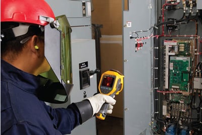 When scanning a live electrical panel, wear appropriate 70E personal protective equipment for arc flash and stand at least 4 feet away.
Point three: emissivity
Emissivity describes how well an object emits infrared energy, or heat. This affects how well a thermal imager can accurately measure the object’s surface temperature. Different materials emit infrared energy in different ways. Every object and material has a specific emissivity that is rated on a scale of 0–1.0. For thermal imagers to report accurate temperatures, the higher the emissivity, the better.
Objects that have high emissivity emit thermal energy well and are not usually very reflective. Materials that have low emissivity do not emit thermal energy well and are usually fairly reflective. This can cause confusion and incorrect analysis if you are not careful. A thermal imager can only accurately calculate the surface temperature of an object if the emissivity of the material is relatively high or the emissivity level on the imager is set close to the emissivity of the object.
Most painted objects have a high emissivity of about 0.90–0.98. Ceramic, rubber, and most electrical tape and conductor insulation have relatively high emissivities as well. Aluminum bus, however, is very reflective, and so are copper and some kinds of stainless steel.
The good news is that most thermal imaging performed for electrical inspection is a comparative, or qualitative, process. You do not usually need a specific temperature measurement. Instead, look for a spot that is hotter than similar equipment under the same load conditions that you do not expect.
Troubleshooting electrical systems
If you are chasing breaker problems or load performance issues, check for hot spots. Once you have completed your repairs, take another thermal scan. If the repair was successful, the hot spot you first detected should have gone away. It is important to note that not all electrical hot spots are loose connections. For a correct diagnosis, it is smart to have a qualified electrician either perform the thermal scan or be present while it is finished. There are several areas to check when troubleshooting.
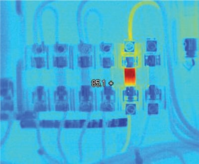 When evaluating an electrical hot spot, notice whether the heat continues back along the wire toward the load (load-related problem) or is isolated to the connection (connection-related problem).
Three-phase imbalance
Capture thermal images of all electrical panels and other high-load connection points, including drives, disconnects, and controls. Wherever you discover higher temperatures, follow that circuit and examine the associated branches and loads.
Compare all three electrical phases side by side and check for temperature differences. A cooler-than-normal circuit or leg might signal a failed component. More heavily loaded phases will appear warmer. Hot conductors may be undersized or overloaded. However, an unbalanced load, an overload, a bad connection, and harmonics can all create a similar pattern, so follow up with electrical or power quality measurements to diagnose the problem.
Voltage drops across the fuses and switches can also show up as unbalance at the motor and excess heat at the root trouble spot. Before you assume you have found the cause, double check with both a thermal imager and a multimeter or clamp meter to measure current draws.
Connections and wiring
Look for connections with higher temperatures than other similar connections under similar loads. They could indicate a loose, overtightened, or corroded connection with increased resistance. Connection-related hot spots usually, but not always, appear warmest at the spot of resistance, cooling with distance from that spot. In some cases, a cold component is abnormal due to the current being shunted away from the high-resistance connection. You may also find broken or undersized wires or defective insulation. The InterNational Electrical Testing Association (www.netaworld.org) guidelines say that when the difference in temperature between similar components under similar loads exceeds 15°C (~25°F), immediate repairs should be undertaken.
Fuses
If a fuse shows up hot on a thermal scan, it may be at or near its current capacity. However, not all problems are hot. A blown fuse, for example, produces a cooler than normal temperature.
Motor control centers
To evaluate a motor control center under load, open up each compartment and compare the relative temperatures of key components: bus bars, controllers, starters, contactors, relays, fuses, breakers, disconnects, feeders, and transformers. Incorporate the previously mentioned guidelines for inspecting connections and fuses and identifying phase imbalance. Measure the load at the time of each scan, so that you can properly evaluate your measurements against normal operating conditions.
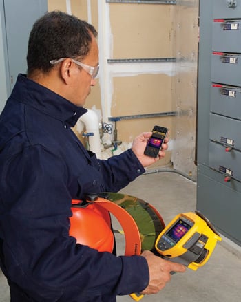 Create an inspection report while still at the inspection site and communicate directly to your client or manager via your smartphone or tablet computer.
Transformers
For oil-filled transformers, use a thermal imager to look at high- and low-voltage external bushing connections, cooling tubes, and cooling fans and pumps, as well as the surfaces of critical transformers. (Dry transformers have coil temperatures so much higher than ambient that it is difficult to detect problems with thermal imagery.) Incorporate the guidelines for connections and imbalances. The cooling tubes should appear warm. If one or more tube is comparatively cool, oil flow is probably restricted. Keep in mind that like an electric motor, a transformer has a minimum operating temperature that represents the maximum allowable rise in temperature above ambient (typically 40°C). A 10°C rise above the nameplate operating temperature will probably reduce the transformer’s life by 50 percent.
*For PPE guidelines, see National Fire Protection Association (www.nfpa.org) Standard 70E Tables 130.7 (c)(9)(a), (c)(10), (c)(11).
About the Author Tony Shockey, thermography product specialist at Fluke Corporation, is a level III thermographer certified in compliance per ASNT standards. He has worked in a variety of industries, including automotive, water and wastewater, oil and gas, and systems integration with a process control and automation background. Shockey has been with Fluke nearly nine years, including two years with the thermography business unit.
Connect with Tony:![]()
A version of this article also was published at InTech magazine.
