Introduction
Pumps, compressors, and distillation columns are commonly used in the process industry. Measuring the pressure or head of the system requires a pressure gauge or sensor. Because of faulty installation or variations, remote pressure sensors or local pressure gauges can produce unexpected results. They occasionally perplex the process engineer, such as when downstream pressure exceeds upstream pressure in the flow direction. Here, we will look at all the issues concerning pressure sensors and value discrepancies. This blog will provide knowledge of pressure measurement as well as recommendations.
When a fluid travels or flows through a pipeline, pressure is classified into two categories: Static and dynamic. An installed pressure sensor typically detects or experiences the static pressure only. If the pressure gauge is tapped in the streamline, it also measures the dynamic pressure. The sum of static and dynamic pressure is known as total pressure; total pressure is always greater than the static pressure, except when dynamic pressure is zero.
Here are some examples of pressure transmitter installation issues that cause erratic pressure readings, such as when the pressure downstream in the flow direction is greater than the pressure upstream, the pressure in the heat exchanger outlet is greater than the pressure in the inlet, and the pressure at the bottom of the vessel is lower than the top and pressure at the bottom of the distillation column is lower than the top. Such reading discrepancy leads us to believe that the transmitter is malfunctioning, although it is possible that the pressure measurement tape was fitted incorrectly.
1. Altitude of pressure transmitter: When pressure transmitters are located far below the tapping elevation, the transmitter tubing becomes liquid-filled, and this liquid exerts some excess pressure owing to the liquid head. Extra pressure must be read by the pressure sensor if the transmitter is not compensated or calibrated as a wet leg. This is solely a liquid service or condensing vapor application, such as steam, propylene, or a heavier hydrocarbon vapor.
Another source of worry is that the transmitter is elevated above the tapping in the process, which contains condensing vapor that can condense at ambient temperatures. Condensate will fill the tubing, and the transmitter will read a different pressure than the actual. In such circumstances, the tubing should be self-draining or compensated for extra leg.
Refer to Figure 1 to see the three different pressure transmitters elevated at different height. Due to altitude, all three would produce different readings in the same pipeline. P1 sensor reads a low pressure because it is filled with liquid, whereas P3 shows a higher pressure due to the liquid head. P2 is perfectly installed and well elevated.
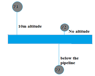 Figure 1
In distillation tower pressure gauge or sensor installed in downcomer by mistake, this will also read as an extra head of liquid. These need to be checked during the design phase. In distillation towers, where vapor can condense at ambient temperature, pressure sensor tubing must be self-draining or positioned at the same elevation.
2. Pressure momentum: Unknowingly, pressure taping is placed in front of the nozzle in many operations, where the high-velocity fluid comes and strikes the tape. This pressure sensor measures static pressure as well as the additional fluid momentum induced by dynamic pressure. Because this pressure meter measures both dynamic and static pressure, it always reads greater than any other adjacent transmitter. Feed nozzle or reboiler outlet nozzle fluid might hit the pressure sensor and cause abnormal readings in compressor knock-out drums, separator vessels, and distillation columns. In a distillation column, a pressure gauge installed at the bottom (above the maximum expected liquid level) of the column can also read higher pressure than normal due to momentum.
3. At the elbow of the pipeline: Pressure sensors or gauges should not be installed at the elbow of the pipeline in any service. Liquid flows due to pressure difference, and it will contain static as well dynamic pressure. When it is installed at the elbow, it senses the dynamic pressure also and shows a higher reading.
Cooling water is flowing via a pipeline, and three pressure sensors are mounted at various points. The first pressure sensor is implanted upstream of the elbow, the second on the elbow, and the third downstream of the elbow. P2 will have a higher reading than P1 and P3. Figure 2 is a simple representation of this. The P2 sensor sees the momentum or velocity head of the flowing fluid and shows the reading of total pressure (static pressure and dynamic pressure).
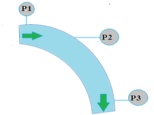 Figure 2
4. At the pipeline instead of the tank: In the process industry, vessels or surge tanks are used to store hydrocarbons, either as a suction drum of a pump or as a feed drum to a plant. These tanks were constantly pressurized with inerts such as nitrogen or fuel gas to impose pressure to assist the pump's net positive suction pressure (NPSP) and to prevent any intrusion from the environment.
A pressure transmitter (as seen in Figure 3) is fitted to maintain pressure in the tank or vessel, and pressure is maintained in the tank or vessel using a PIC controller or PCV. Pressure sensors are installed in the pipeline (P2) rather than the tank (P1) in some plants. These pressure sensors would read deviation due to flow of gas. There is a continual flow of nitrogen or hydrocarbon vapor through the nitrogen pipeline or vent line, and the vessel or tank’s top would not properly manage the pressure. It would occasionally remain lower than planned, while other times it would remain higher than set points. So, pressure sensors always should be installed on the vessel or tank directly such as P1 instead of P2 to control the static pressure of the vessel accurately.
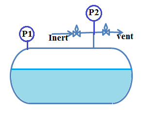 Figure 3
5. Before a fully developed flow: In fluid mechanics, we address the boundary layer separation phenomenon. The boundary layer divides when fluid enters the pipelines, and the velocity profile of the fluid across the pipeline alters until it fully develops. This velocity profile is also affected by whether the fluid is flowing laminarly or turbulently. Due to the turbulent nature of most fluid flows, the pressure sensor should be fitted after the flow has been fully developed. The velocity profile in fully developed flow is parabolic in laminar and somewhat flatter in turbulent, and the velocity near the wall is virtually nil. To obtain the accurate measurement, a pressure sensor should be inserted after the fully developed flow or after the entrance length. The pressure near the wall is merely static pressure, and the sensor only reads static pressure rather than total pressure.
6. Plugging/chocking/coking of tubing: Many processes in the process industries use congealing, slurry, heavy tar, or coke material. Pressure measurement is difficult in such a process. This tar or coke can deposit in the pressure sensor tubing and jam or choke the pressure transmitter tube, causing it to report an erroneous pressure and mislead the operator about the process. To minimize direct contact between the viscous or thick slurry and the pressure sensor, several industries adopted a remote-seal pressure sensor. However, in a remote seal, a diaphragm monitors pressure, which is then converted by the transmitter. This coke or slurry can deposit on the diaphragm, necessitating the use of an external fluid to flush the deposited material. Examples of such services are slurry circulation in FCCU and heavy oil in DCU and quench oil circulation in steam cracker units.
7. Flushing/purging with external fluid: Congealing services or viscous materials capable of solidifying at ambient temperature are required for some flushing, as previously indicated. External fluid flushing is also required to remove the accumulated material. External flushing fluid should be compatible with pipeline fluid or internal fluid. Steam, nitrogen, or any other appropriate liquid can be used as external fluids. External high-pressure fluid is fed into the pressure sensor tube or diaphragm when a pressure sensor is installed in this type of congealing or viscous operation.
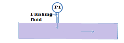 Figure 4: Flushing fluid injection
These high-pressure external fluids generate tremendous velocity to flush the deposited materials. The pressure sensor detects this high velocity of the external fluid and reads an incorrect value because the low-pressure zone near the pressure sensor's diaphragm or tubing is caused by the rapid and high velocities of the external fluid (see Figure 4). Because of inadequate flow metering, the flow of external fluid or purging gas is very high in some plants. This high flow can result in a high-pressure reading due to pressure accumulation or buildup.
8. After expander of pipeline: The process industry pipeline is laid throughout the plant and contains numerous elbows, tees, and expanders. According to the Bernoulli principle, as the area of the pipeline expands owing to expansion, the velocity slows, and the kinetic energy is turned into pressure energy. As a result, the pressure sensor downstream (P2) detects a higher pressure than the pressure sensor (P1) upstream (see Figure 5). This is also true vice versa.
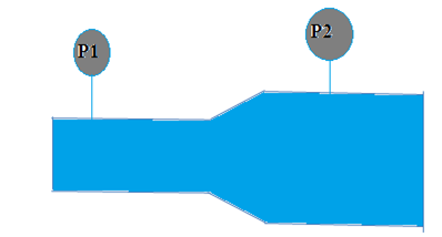 Figure 5: Pressure sensor after expander
9. Dual phase pressure measurement: When process stream contains the condensing vapor or dual phase in the pipelines, pressure values can be surprising due to condensation. When vapor is flowing through the pipelines, at one point the pressure sensor reads a certain pressure value. However, due to heat loss or any cooler (heat exchanger), that vapor would partially condense, slowing the velocity of the dual phase slightly due to condensation and increment in the pressure. This signifies that the pressure downstream of the cooler, or heat loss owing to ambient, is larger than the pressure upstream. It might be surprising, but this happens due to the Bernoulli’s principle or “effect,” as described in more detail in reference 7.
Conclusion
A pressure sensor or pressure measurement is the most basic equipment for reading pressure, although the reading might be perplexing or misleading due to installation alteration. These are some recommendations to avoid such design errors and erratic pressure readings:
- Always use siphon tubes or liquid filed tubing in steam or high temperature services to avoid direct contact of steam with pressure gauges or transmitters.
- Always calibrate pressure sensors based on situation wet and dry leg.
- Pressure sensor should be away from the momentum of fluid and elbow of the pipeline.
- Always check plugging, chocking, or coking of the tubing of pressure transmitters and flush the transmitter tubing with compatible fluid in intervals.
- Always install pressure sensor 10D after the mixing point to get fully developed flow.
- A pressure sensor must be put directly on the vessel or tank instead of the pipeline if continuous static pressure is to be maintained in the tank or vessel.
- Always utilize remote seal pressure sensors in corrosive or caustic environments.
- During the continual flushing of pressure sensors, the flushing flow should be monitored.
- In distillation columns, pressure sensors should be installed in vapor phase and checked during the design phase to avoid downcomer installation.
Note: This blog is not related to any specific company and is based on author experience and learning for knowledge-sharing only.
References
- Wikimedia Foundation. (2022, October 4). Pressure measurement. Wikipedia. Retrieved January 5, 2023, from https://en.wikipedia.org/wiki/Pressure_measurement
- Lieberman, N. P., & Lieberman, E. T. (2014). Working Guide to Process Equipment. McGraw-Hill Education.
- Sharma, A. (2022, April 1). The Flaws of Flow Meters. Retrieved January 5, 2023, from https://blog.isa.org/the-flaws-of-flow-meters
- Kister, H. Z. (1990). Distillation Operation. McGraw-Hill Education.
- Sharma, A. (2022, July). Caustic tower design guidelines and recommendations. Hydrocarbon Processing. Retrieved January 5, 2023, from https://www.hydrocarbonprocessing.com/magazine/2022/july-2022/process-optimization/caustic-tower-design-guidelines-and-recommendations
- Baukal, C. E. (2013). The John Zink Hamworthy Combustion Handbook. CRC Press.
- Lieberman, N. P. (2017). Process Engineering: Facts, Fiction and Fables. Wiley.