This post was written by Greg McMillan, industry consultant, author of numerous process control books, 2010 ISA Life Achievement Award recipient and retired Senior Fellow from Solutia Inc. (now Eastman Chemical).
The installation of the sensor can introduce errors, noise, and dynamics causing poor measurement and control loop performance. Here we look at best practices to get the most out of the inherent capability of the sensor. In another post, I plan to provide guidance on the communication of the sensor signal to the control room to provide the best total installation.
Thermowell Length
To minimize conduction error (error from heat loss along the sensor sheath or thermowell wall from tip to flange or coupling), the immersion length should be at least 10 times the diameter of the thermowell or sensor sheath for a bare element. Thus, for a thermowell with a 1 inch (2.54 cm) outside diameter, the immersion length should be 10 inches (25.4 cm).
For a bare element with a ¼ inch (6.35 mm) outside diameter sensor sheath, the immersion length should be at least 2.5 inches (63.5 mm). This is just a rule of thumb. Computer programs can compute the error and do a fatigue analysis for various immersion lengths and process conditions. For high velocity stream and bare element installations, it is important to do a fatigue analysis because the potential for failure from vibration increases with immersion length.
Thermowell Location
The process temperature will vary with process fluid location in a vessel or pipe due to imperfect mixing and wall effects. For highly viscous fluids such as polymers and melts flowing in pipes and extruders, the fluid temperature near the wall can be significantly different than at the centerline (e.g., 10 to 30°C; 50 to 86°F). Often the pipelines for specialty polymers are less than 4 inches (101.6 mm) in diameter, presenting a problem forgetting sufficient immersion length and a centerline temperature measurement. The best way to get a representative centerline measurement is by inserting the thermowell in an elbow facing into the flow (position 1 in the figure below).
If the thermowell is facing away from the flow, swirling and separation from the elbow as can create a noisier and less representative measurement (position 2 in figure). An angled insertion (position 3 in figure) can increase the immersion length over a perpendicular insertion (position 4 in figure) but the insertion lengths shown for both are too short unless the tip extends past the centerline. A swaged or stepped thermowell can reduce the immersion length requirement by reducing the diameter near the tip. 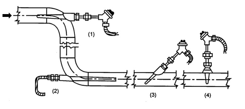 The distance of the thermowell in a pipeline from a heat exchanger, static mixer, or desuperheater outlet should be optimized to reduce the transportation delay but minimize noise from poor mixing or two phase flow. Generally 25 pipe diameters are sufficient to ensure adequate mixing from turbulence if there is a single phase, turbulent flow, and no great differences in the viscosity of streams being combined.
Two phases exist for desuperheaters, split ranged transitions from cooling water to steam in jackets, the use of lime ammonia as a reagent for pH control due to flashing and whenever slurries are involved. The transportation delay will increase with distance adding more dead time to the loop. Consequently, there is a compromise between getting enough mixing to achieve a representative low noise measurement and creating too much additional dead time. In general, the transportation delay should be less than 10% of the PID reset time setting.
Insight: Generally a distance of 25 pipe diameters between the equipment outlet and the temperature sensor is sufficient to provide a relatively uniform temperature profile of a single phase fluid. The presence of different phases (e.g. bubbles or solids in liquids and droplets in steam) and high viscosity fluids will require longer distances.
For desuperheaters, the distance from the outlet to the thermowell depends upon the performance of the desuperheater, process conditions, and the steam velocity. To give a feel for the situation there are some simple rules of thumb for the length of piping from the desuperheater to the first elbow known as straight piping length (SPL) and the total piping length from the desuperheater outlet to the sensor known as sensor total length (TSL).
The choice of thermowell length, location, and construction determines whether the temperature measurement is representative of the process, how much process noise is seen, how much delay and error is introduced, and the potential failure rate. This post provides general guidance. For more details including the equations to predict eight sources of measurement error see the ISA book Advanced Temperature Measurement and Control, Second Edition.
For a bare element with a ¼ inch (6.35 mm) outside diameter sensor sheath, the immersion length should be at least 2.5 inches (63.5 mm). This is just a rule of thumb. Computer programs can compute the error and do a fatigue analysis for various immersion lengths and process conditions. For high velocity stream and bare element installations, it is important to do a fatigue analysis because the potential for failure from vibration increases with immersion length.
Actual SPL and TSL values depend on the quantity of water required with respect to the steam flow rate, the temperature differential between water and steam, the water temperature, pipe diameter, steam velocity, model, type, etc. and are computed by software programs. SPL (feet) = Inlet steam velocity (ft/s) x 0.1 (seconds residence time) SPL (m) = Inlet steam velocity (m/s) x 0.1 (seconds residence time) TSL (feet) = Inlet steam velocity (ft/s) x 0.2 (seconds residence time) TSL (m) = Inlet steam velocity (m/s) x 0.2 (seconds residence time) Typical values for the inlet steam velocity, upstream of the desuperheater range from 25–350 ft/s (7.6 to 107 m/sec).
Below 25 ft/s there is not enough motive force to keep the water suspended in the steam flow. Water tends to fall out and run down the pipe to a drain. When this happens the water no longer cools the steam and the system thinks it needs to add more water, which compounds the problem. Problems can also include pipe wall erosion and high thermal stress gradients in the pipe wall (i.e., a hot top and cold bottom, which can crack welds or warp the pipe to an egg-shaped cross-section). Current technology has an inlet velocity limitation of 350 ft/s (107 m/sec). Velocities higher than 350 ft/s cause the desuperheater to vibrate and damage the unit to the point where it breaks apart.
Thermowell Construction
The stem of a thermowell is the part that is inserted into the process stream. Stems can be tapered, straight, or stepped. The performance of a thermowell varies with its stem design. In general, a tapered or stepped stem provides a faster response, creates less pressure drop, and is less susceptible to conduction error and vibration failure. If the thicknesses of the thermowell walls and the fit of the sensing element are identical, thermowells with straight stems have the slowest time response because they possess the most material at the tip (largest diameter).
Thermowells with stepped stems have the fastest time response because they possess the least material at the tip (smallest diameter). A small diameter also results in the least amount of drag force. Thermowells with stepped stems also provide the maximum separation between the wake frequency (vortex shedding) and the natural frequency (oscillation rate determined by the properties of the thermowell itself). If the wake frequency is 80% or more of the thermowell natural frequency, resonance and probably damage can occur. Generally, thermowells with tapered stems are slightly more expensive as a result of a more complicated manufacturing process.
Insight: Swaged, stepped, and tapered thermowells offer a faster response, lower pressure drop, and less possibility of vibration damage from resonance with wake frequencies.
The tip of the sensor must touch the bottom of the thermowell. Spring loaded sensor designs help ensure this is the case despite different installation practices and orientation. The fit of the sensor should be as tight as possible to reduce the annular clearance since air acts as insulator. The sensor lag can increase by an order of magnitude for a sloppy fit. For liquid systems, the additional lag effectively becomes an additional equivalent dead time in the measurement.
Insight: The tip of the temperature sensor must touch the bottom of the thermowell and the fit must be tight to prevent introducing a large sensor lag due to the low thermal conductivity of air.
Take advantage of general guidelines on thermowell insertion length, location, construction, and fit to make sure the sensor is seeing the actual process temperature with a low probability of vibration failure and minimal noise, delay and lag.
About the Author
Gregory K. McMillan, CAP, is a retired Senior Fellow from Solutia/Monsanto where he worked in engineering technology on process control improvement. Greg was also an affiliate professor for Washington University in Saint Louis. Greg is an ISA Fellow and received the ISA Kermit Fischer Environmental Award for pH control in 1991, the Control magazine Engineer of the Year award for the process industry in 1994, was inducted into the Control magazine Process Automation Hall of Fame in 2001, was honored by InTech magazine in 2003 as one of the most influential innovators in automation, and received the ISA Life Achievement Award in 2010. Greg is the author of numerous books on process control, including Advances in Reactor Measurement and Control and Essentials of Modern Measurements and Final Elements in the Process Industry. Greg has been the monthly "Control Talk" columnist for Control magazine since 2002. Presently, Greg is a part time modeling and control consultant in Technology for Process Simulation for Emerson Automation Solutions specializing in the use of the virtual plant for exploring new opportunities. He spends most of his time writing, teaching and leading the ISA Mentor Program he founded in 2011.
Connect with Greg:
![]()