

This post was wrriten by Augusto Pereira, an ISA Fellow who has served as a professor of engineering and information technology at a number of colleges and universities in Brazil, and Ian Verhappen, P.Eng., CAP, and co-author of A Guide to the Automation Body of Knowledge.
The commissioning and configuration of digital communications of a field-level network, such as Foundation Fieldbus, is fundamental to obtaining certification of the digital communication of the segments and, hence, approval to start up the plant.
Despite the fact that the Fieldbus Foundation (FF) project may have been developed and designed following all concerns, standards, such as ISA-50.02 and IEC 61158-2, and good engineering practices available from several sources, success is not guaranteed. Field construction and assembly made without the same levels of quality can put the plant at risk due to resulting malfunctioning of the networks.
What can we do to ensure reliable FF communications?
We find the worst situation for a fieldbus segment, after having been assembled, is not when a segment does not work at all, but when this segment begins to function erratically. Erratic operations include, for example, failing to communicate and soon resuming network communications. In the first case, the non-functioning is a problem that does not allow that the segment be released, and all efforts must be made to solve the problem. The second case, that of intermittent functioning, in general, is difficult to solve because it requires more study, at times you cannot predict when something can be observed, and many of the base line tests were not executed during the installation of the segment.
 Fieldbus wave shape – high noise
Qualifying the installation and assembly team to work at the level of quality necessary for a field digital network is the beginning of the solution. However, even with fully qualified installation teams, it is still a fundamental requirement to certify the segments. What is certification of a Foundation Fieldbus or Profibus PA segment? The first step is to have a successful installation. To understand better the requirements for a successful installation, we can divide the certification process into six phases.
Inspection during the installation
Inspection during installation is the best procedure, because it is done following each step of the installation starting with tests of the electrical characteristics of the fieldbus cable upon its arrival and in every phase of the construction process. It is also very important to inspect the installation of the grounding to confirm compliance with the project design documents. Additional items to be inspected include:
- Control system Fieldbus Foundation interface
- Power supply and network conditioner
- Cables
- Terminators
- Surge protector and junction boxes
Junction boxes are available in three different configurations and can be classified as:
- Passive, where we have the spurs with no protection against short circuit; we do not recommend its use.
- Active, which offers individual protection against short circuit in every spur; we do recommend its use.
- Field barriers, which connect a non-intrinsically safe trunk to instrinsically safe spurs. The spurs also must have protection against short circuit and galvanic isolation with the trunk.
Proper grounding of the cable shield, instrument case, and fieldbus junction boxes must also be thoroughly checked, as ground loops are often the source of communication problems.
Electrical commissioning
In this phase, we must complete the continuity, isolation, and capacitance measurements of the cable coil when it arrives at the plant and again, later, for each piece of cable before connecting the trunk and the spurs. The recommended values for these measurements from the Fieldbus Foundation are shown in Figure 1:
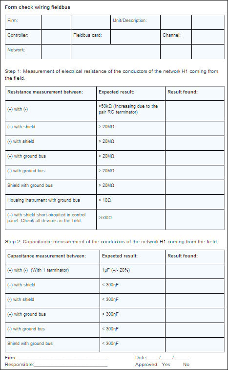 Figure 1. Sample electrical commissioning report
Electronic commissioning
After all cables are connected and energized, we need to check the voltage levels at every instrument and compare them against the value that was calculated during the detail design phase (Figure 2).
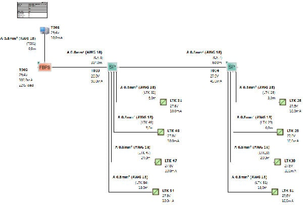 Figure 2. Typical FF/PA segment calculation
If errors are found, the non-conformities must be analyzed and corrected, because we can have differences between the values, which were assumed, or during the detail design phase and differences arising from construction in the field.
Commissioning of the application configuration
Commissioning includes checking the correct connection of the instruments on the segments in the field as compared to what was intended by the people in charge of the configuration. This needs to be verified because some instruments may have changed from one instrument to another, or one segment to another, and the configuration did not receive this information to be updated.
Diagnostics of the digital communication
We now need to check the electronic characteristics of the Fieldbus Foundation signal. In general, we can say that the Fieldbus signal is almost a rectangular wave. The element responsible for the transmission of the data acts as a current source. By alternating the direction of the current flow in the Fieldbus cable, this current variation is transformed by the resistance in the Fieldbus terminators to a voltage. The IEC 61158-2 standard defines the physical layer of the protocol. The ideal wave shape of the Foundation Fieldbus and Profibus PA protocols is shown in the following diagram:
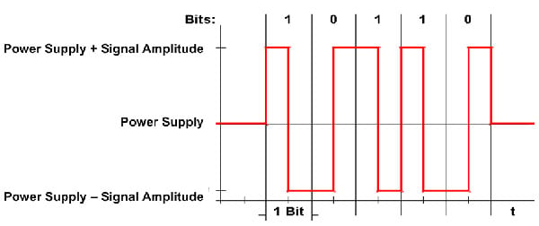 Figure 3. Theoretical wave shape of Fieldbus Foundation
The Fieldbus signal is measured as the differential voltage between the conductors "Fieldbus (+)" and "Fieldbus (-)." One of the main characteristics of the Fieldbus Foundation physical environment is that it has power and data on the same pair of cables, which means a Fieldbus signal will always be a combination of AC and DC signals. To avoid interferences between the two signals, it is important that the AC signal always be free of any component of noise or distortion. The same modulation technique, called Manchester II Code, is used in Foundation Fieldbus and in Profibus PA. A transfer speed of 31.25 Kbps implies a period of 32μs, and an ideal Manchester signal has 50 percent of the period (16μs) at the positive semi-cycle and the other 50 percent in the negative semi-cycle. In practice, a fieldbus signal seems to look more like a trapezoidal wave, and its trajectories of ups and downs are diagonal due to the capacitances and inductances present in the components of the physical layer. These inductances and capacitances are responsible for the presence of distortion and overshooting of the signal.
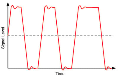 Figure 4. Actual fieldbus wave shape
Measuring physical layer diagnostics
The following variables must be measured with the diagnostic tools:
- Signal level
- Voltage in the segment
- Current in the segment
- Unbalancing
- Noise and wave shape
- Jitter
Signal level The signal level is defined by the norm IEC 61158-2 as:
- 0.75Vpp to 1Vpp @ 50 Ohms for transmission
- Reception signal > 150m Vpp
An example of a wave shape with problems in the fieldbus network can be seen below. In this case, the network has fewer than the required number of two terminators.
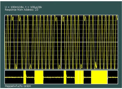 Figure 5. Fieldbus wave shape - elevated amplitude
Unbalancing As mentioned previously, the H1 signal has a rectangular wave shape, modulating in current that will be measured as a differential signal between the conductors. It is also necessary that the signal be symmetrical to the power signal and balanced in relation to 0V.
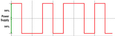 Figure 6. Balancing of signal
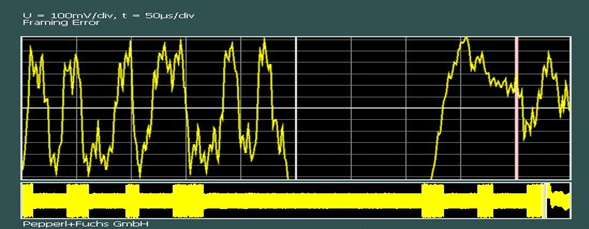
The balancing is an indicator of sensitivity to noise or other interferences a Fieldbus network is exposed to. Noise and wave shape One of the effects of the unbalancing is an increasing sensitivity to noise. IEC 61158-2 defines the limits of noise created by the power supply/conditioner and by the field devices. The wave shape in Figure 7 illustrates a network failure caused by excess noise.
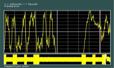 Figure 7. Fieldbus wave shape - high noise
Jitter Jitter is an extremely important variable in the fieldbus communication. "Jitter" means the deviation of the midpoint or transition point of the bit related to the "crossing zero point." Jitter is caused by signal distortion, noise, and resonance of the network.
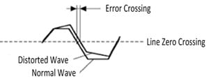 Figure 8. Jitter
Generation of the communication certification report
This is the final phase of the work, and the values found are compared against the IEC 61158-2 standard. The certification report will show verification for every component of the segments and contains information as shown in Figure 9:
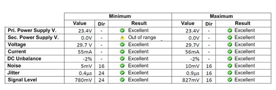 Figure 9. Model of the measuring table of certification of the FF/PA segment
Conclusion
This was an experience in a recently completed certification job. For approximately one year, the plant was seeing intermittent communication problems, and, even with the diagnostics values operating within the specification limits of the IEC 61158-2 standard, a communication problem was happening. Figure 10 shows the wave shape on the segments in which the communication failures were more frequent:
 Figure 10. Fieldbus wave shape with distortion
Interestingly enough, although the electric values were good, the wave shape was distorted. So, what was the reason for the distortion? Over time, the client had hired three companies to investigate the problem, and all of them concluded that the segments were faulty, but they were not able to explain the reason for the communication errors. This was one of the strangest cases seen since 1994, when we had our first contact with the Fieldbus Foundation technology. Our friend, Professor Marcos Peluso, would say in times like these that it is very important to keep calm and go out of the common way of thinking.
At the time, with no idea what caused the problem and the contract was ending, no one had yet been able to determine the possible cause of the problem. On the day of the contract termination date, it was time to go back to basics and ask the following questions: What was the actual function of the diagnostics? What did they search? What, indeed, could we conclude from values we had examined? Then came the "Aha!" moment, when a solution was found: the diagnostic analysis showed the characteristics in a static way, but the dynamics of the communication are much more complex.
Because the transmission line, which is an FF/PA segment, also true for many other protocols, the performance depends on the impedance of the line, and distortions may happen with variations of frequency and communication traffic patterns at various times. These changes are dynamic, and we were only looking at static data. Time to look more carefully at the cable that was installed, and, to our surprise, by external appearance, the cable seemed like a fieldbus cable; it had the same color, but this doesn't mean anything because a manufacturer can produce a cable with any color the client requests; it had the same diameter, but this also means almost nothing. But... we did not know what manufacturer was used to supply the cable.
After checking on the Fieldbus Foundation website it was discovered that the manufacturer's product was not tested and certified. This is when the light switched on: this had to be the reason! After analyzing more thoroughly, it was confirmed that there were segments with cables from manufacturers certified by the Fieldbus Foundation that had practically no errors, while other non-certified cables exhibited the common communication problems. The lesson learned: "Don't judge a cable by its jacket." A final note: In order to have guarantees of good performance, a project with a field digital protocol needs to at least follow the steps described in this article, and the use of certified products is fundamental to achieving overall success.
About the Author
Augusto Pereira is an ISA Fellow and has served as a professor of engineering and information technology at a number of colleges and universities in Brazil. Since 1994, he has been involved in more than 241 automation projects with digital protocols in Brazil, Canada, Argentina, Chile, Colombia, Venezuela, Cuba and Peru. In South America, he has worked for Dow Chemical, Emerson Automation Solutions, Yokogawa and Pepperl+Fuchs. Augusto was president of District 4 (South America) of ISA from 1998 to 2000, and currently is the ISA District 4 director of events and exhibitions.
Connect with Augusto![]()
About the Author
Ian Verhappen, P.Eng., CAP, is a senior project manager at CIMA+ where he specializes in industrial communications networks, including Foundation Fieldbus technology; control system migrations/upgrades; process analyzers; sample systems; and oil sands automation. Ian, an ISA Fellow, has been involved in digital communications since 1994. He helped to install the first multi-vendor Foundation Fieldbus project in 1996. Since then, he has served as both a project engineer/designer and an external review consultant for a number of companies in pulp and paper, mining, food processing, water and wastewater, oil sands processing, petrochemical and refining industries. Ian is an active ISA volunteer leader, serving as Vice-President of ISA Standards and Practices and a former ISA District 10 Vice President. As a leader in automation practices, he has worked closely with the Standards Council of Canada and the International Electrotechnical Commission (IEC). He currently serves as Canadian Chair of IEC TC65, SC65B and SC65E. He is co-author of several ISA books, including A Guide to the Automation Body of Knowledge and Foundation Fieldbus. An inductee into the Process Automation Hall of Fame, Ian earned a bachelor of science degree in environmental science and a bachelor of chemical engineering degree, both from the University of Alberta.
Connect with Ian![]()
![]()
A version of this article also was published at InTech magazine.
