This post was written by Paolo Pinceti and Micaela Caserza Magro of the University of Genoa.
Recently, the International Electrotechnical Commission (IEC) approved a new standard for the specification and evaluation of process control systems (PCSs) in industrial applications: IEC 62603, "Industrial Process Control Systems – Guideline for Evaluating the Performances of Process Control Systems – Part 1: Specifications."
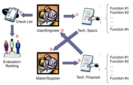
The process of specifying, choosing, and testing a process control system for an industrial application is long, time consuming, and risky (figure 1). The engineering company or the end user prepares the technical specifications of the required PCS and sends them to a set of companies that produce or integrate PCSs. Hopefully, the specifications contain all the necessary and useful functions for controlling the process. Each candidate supplier verifies that its system fulfills all the requirements, prepares its proposal, and sends it back to the engineer. Preparing the proposal requires a clear comprehension of the requirements; misinterpretations are likely to happen in this step. The engineer (or end user) prepares a checklist to verify the degree of compliance of every proposal and ranks all the acceptable proposals.
Hopefully, the specifications contain all the necessary and useful functions for controlling the process. Each candidate supplier verifies that its system fulfills all the requirements, prepares its proposal, and sends it back to the engineer. Preparing the proposal requires a clear comprehension of the requirements; misinterpretations are likely to happen in this step. The engineer (or end user) prepares a checklist to verify the degree of compliance of every proposal and ranks all the acceptable proposals.
Today this process has several critical points:
- each engineering company or end user uses its own forms and company standards for writing the specifications
- the specification may lack some of the important functions or requirements
- being "company specific," the maker of the PCS might misunderstand some definitions or requirements, leading to either under- or overevaluating the bid
- the process of evaluation may require comparisons of features that are difficult to quantify
- ranking the proposal is not transparent if a metric is not predefined
These problems prompted a group of end-user members of the international association Exera to study a standardized procedure for specifying and testing PCSs. They started a research project with the University of Genoa in Italy to find a solution for both the users and the makers of process control systems. Their document was submitted to the members of the Italian regulating body (CEI), which decided to propose a new standard to IEC. The proposal was presented, and a large majority of members of IEC accepted it. The Technical Subcommittee 65B (Measurements and Control Devices) assigned the task of preparing the new standard to the Working Group WG6 (Testing and Evaluation of Performances). The scope of WG6 is "to prepare methods of evaluating the performance of system elements and functions used in industrial process measurement and control with special regard for harmonization." An international group of 22 experts from 10 countries began working in 2009 and continued through all the phases of standard production until June 2013, when the standard was approved with 18 out of 19 votes. The WG6 has liaisons with other IEC subcommittees and external associations, such as Exera, Profibus Network Organization, and Foundation Fieldbus, that cooperated in the production of the standard.
Scope of IEC 62603
It must be clearly stated that the IEC 62603 is not a product standard for control systems (like, for example, the IEC group of standards IEC 61131 that defines systems based on programmable logic controllers [PLCs]). IEC 62603 is intended to be used for specifying, comparing, and testing a PCS for a well-defined application. It includes all the requirements that should be specified to make the PCS fulfill the control requirements of the process.
The final goal of IEC 62603 is to define a set of methods and tests to evaluate and assess the performance of a PCS for a given application in terms of functions, applications, static and dynamic performances, and compatibility. The standard has two parts:
- Part 1 is a guideline preparing the technical specifications of a PCS, including all the functions and services required of the PCS for a given application.
- Part 2 (future) contains the procedures of the factory acceptance test (FAT) and the requirements that have been specified according to Part 1.
The first part of specifying and testing a PCS is mostly paperwork (figure 2). The engineer or end user defines the PCS requirements and compares the technical proposals from the vendors with the help of Part 1 of IEC 62603. The chosen vendor assembles the PCS and implements the application software (i.e., the required control logic for the process). When the system is ready, vendor and engineer/end user agree on the procedures of the FAT using Part 2 of the standard as a reference.
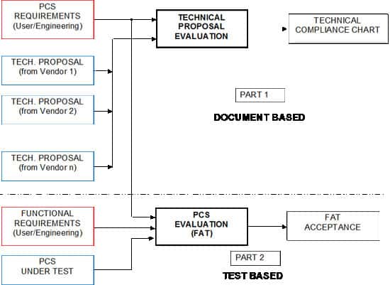 Figure 2. Figure 2. Use of IEC 62603 in the process of PCS specification and testing
The standard includes a procedure for calculating a quality index of a PCS (a vote), based on compliance with the specified functions and technical characteristics. This index may be used by the engineer/end user for ranking the various proposals, but the vendor may also use it for a self-evaluation of his or her product or system.
IEC 62603 contains the specifications for both conventional control systems and for up-to-date systems that extensively use digital communication technologies.
To create a ready-to-use guideline, the experts of WG6 decided the IEC 62603 should include the relevant parts of other IEC standards that deal with specific aspects of a PCS. In other words, when a given aspect is considered in another IEC standard (e.g., climatic conditions, immunity, fieldbus) the information necessary to make a selection or a choice is included in the guideline. The user of IEC 62603 should verify that no more recent version of the other cited standards exists.
Technical specifications of a PCS
A large amount of data should be specified for a PCS. The IEC 62603 divides the data into eleven sections summarized below.
System architecture
The specification of the PCS should define the general characteristics of the required system and include a preliminary drawing of the architecture. After this, each maker proposes a detailed architecture of a PCS according to the devices he or she produces or uses. Figure 3 is an example of the level of detail of the architecture to include in the specification.
It is very important that the engineer/end user specifies both the technology and the function of the PCS. A system may be composed of a mix of technologies and may perform more than one of the functions listed in table 1.
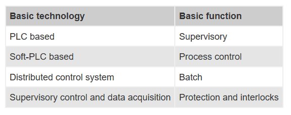 Table 1. Basic technologies and functions of a PCS
In addition to the basic architecture, the engineer/end user should specify the rough data that affects the PCS dimensioning and computational power (i.e., the number of I/O and the number of control loops to manage with the PCS). In some industrial areas, mainly in the continuous processes, it is common to indicate the number of tags or process objects the PCS should control.
Installation environment
The specification of the installation environment includes several aspects, from the climatic conditions to the power supply and mechanical conditions. The basic parameters to specify are:
- class of location (IEC 60654-1) for devices in the control room, the electrical rooms, and the field
- quality of the auxiliary power (IEC 60038) both in AC and in DC, including expected voltage and frequency variations, harmonic content of the voltage, and switching time (when applicable)
- EMC requirements, mostly in terms of immunity to radiated and conducted disturbances (IEC 61326-1 and others)
- mechanical vibrations and corrosive influences
- classification of the hazardous areas (IEC 60079-10-1 for gases and 60079-10-2 for dusts), mostly for devices installed in the field
System characteristics
The two basic requirements of the system to specify here are:
- scalability, the ability of a system to grow larger without having to replace parts
- expandability, the possibility of enlarging each component of the system without changing the architecture or the component itself
Other system aspects that should be specified are:
- the procedures for configuring the system
- the possibility of changing the configuration on the run
- the supported programming languages (IEC 61131-3), including batch management (IEC 61512)
System dependability
Dependability defines the availability of a system in terms of reliability, maintainability, and maintenance support (IEC 62347 and IEC 60300-3-4). Dependability summarizes the capacity of a system to perform its tasks in a given time or time interval. Reliability of a system (IEC 61078 and IEC 61025) is strongly influenced by:
- the self-diagnostic functions to detect failures or defects
- the possibility of hot swapping components to substitute failed components without affecting system operations
- the redundancy of critical components (e.g., two out of three)
Figure 4 shows the response of a PCS to component failure. A noncritical failure leads the PCS into a degraded operating mode, where the essential functions are still available. On the contrary, a critical failure of a component that is not redundant sets the PCS in failed mode, where one or more critical functions are no longer available. If the failed component is redundant, then the PCS still fully operates, but in emergency mode. Another failure would set the PCS into failed mode. Repair actions move the PCS into a safer status. Repair actions strictly depend on the ability of the system to alert the user and request maintenance service when a device or subsystem reaches its limits.
Dependability of the PCS also influences its ability to be part of a safety instrumented system (IEC 61508). If the plant requires safety-related functions with a specified safety integrity level (SIL), the engineer/end user should specify how to integrate safety systems in the overall PCS architecture. Figure 5 shows some typical solutions for integrating the basic process control system (that actuates the normal control logic) and the emergency shutdown system (that actuates the safety-related functions):
- integrated: basic process control system and emergency shutdown system share the same communication infrastructure
- common: a unique system performs both normal and safety functions (only for low SIL values)
- separated: no connection between basic process control system and emergency shutdown system
I/O specification
A PCS may have several types of I/O, both conventional (i.e., 4–20 mA) and digital (i.e., fieldbus). For each specified I/O type, the user should specify the desired values in terms of accuracy, resolution, and repeatability (IEC 60050). Important issues to specify are the possibility of hot swapping the I/O cards and their self-diagnostic capacities.
Software requirements
The structure of the software makes the difference between the various types of systems. Of utmost importance is how the data is stored to use in real-time applications. Two classes of database exist:
- distributed database: data is stored in multiple physical locations connected in a network
- concentrated database: data is continuously transmitted to/from a central database, and all the applications access data through it
Security issues of the system are defined here in terms of both access management and cybersecurity (IEC 62443-2-1 and 62443-3-3).
Human-machine interface
Human-machine interface (HMI) includes all the devices and methods used to interface with the PCS, e.g., displays, PC monitors, and software tools. HMI is both in the control room and in the field, and requirements are obviously quite different. Possibly the most important function of HMI is presenting the alarms from the process and from the PCS itself to the operators. Alarms can be organized into priority levels (ANSI/ISA-18.2 and the future IEC 62682) according to the consequences of the anomaly that caused the alarm and the allowable response time. Together with alarms, event management also has to be specified, especially if short time resolution is required (function: Sequence of Events). Historical archiving, data searching and display (e.g., trends), and data backup functions are all included in the HMI.
Communication requirements
Communication is the core of any modern PCS. A PCS with a high level of integration may have up to four levels of communication (figure 6):
- fieldbus: from/to field devices, to/from the controllers
- controller network: the backbone of control functions, it connects all the controllers
- control room network: based on IEEE802-Ethernet, connects the controllers to the computers in the control room
- corporate network: integrates the PCS in the information and communication technology environment of the company
Simpler PCSs may require fewer communication networks. Less-demanding applications do not have the servers, and the controller network and the control room network are joined together.
The engineer/end user should specify the protocol to use for each network and the interfaces (if any) with other external systems, such as manufacturing execution systems or enterprise resource planning. Communication with external subsystems or third-party systems should be specified in detail to set clear requirements.
Required performances
Performances are often related to specific functions that the PCS, or a part of it, should perform within strict time constrains. The most typical functions of this type are:
- synchronization of peripherals (e.g., remote I/O or intelligent devices)
- call-up time for the HMI pages, including the time for uploading the variables
- overall response time of the HMI, from the time the operator initiates a command to the time the feedback displays on the monitor
- controller cycle time, mainly for hard real-time control functions
In some cases, specific key performance indicators are defined to monitor the performance of devices or subsystems. In manufacturing and in batch processes the overall equipment effectiveness is calculated mainly to measure the efficiency of a process or machinery.
Life-cycle support
The support of a PCS starts during the presale stage and continues throughout its whole life cycle. It includes technical services (e.g., training, online service, spare parts) and commercial aspects (e.g. warranty, software updates).
FAT specification
The general aspects of the factory acceptance test, site acceptance test, and site integration test are described in the group of standards IEC 61069 and 62381. Detailed procedures for testing all the functions of a PCS are in the scope of the future IEC 62603-2. Nevertheless, the engineer should specify the type and the extent of the testing in the technical specification of the PCS. The first steps of a FAT are always:
- check the project documentation
- check the hardware supply (bill of material)
- inspect the whole system visually
- check that each device operates as expected
In addition to these steps, the user should specify the type of FAT required for the application software, i.e., the software that is specific for this project. IEC 62603 defines five levels of increasing depth for the FAT of the application software (figure 7):
- level 1: tests are carried out using the HMI of the PCS, and no external mock-up is required
- level 2: the engineer manually forces the I/O with a software tool for checking the application software feedback
- level 3: the test includes the terminations of the PCS. I/O is tested with hardware simulators that inject the physical signals into the PCS terminals.
- level 4: mainly applicable to integrated PCSs with fieldbus connections to the field devices. Specific cards that allow emulating the connected devices simulate the traffic on the fieldbus. The engineer manually enters the values of the variable.
- level 5: the architecture is identical to level 4, but the values of the variables are calculated by a software process simulator. The simulator also dynamically calculates the feedback from the process to check control logic. (For details see "To emulate or to simulate, that is the question.")
Once the level of the test is defined, the user should specify the level of coverage of the tests. Partial tests may be sufficient for repetitive functions, while other functions (e.g., safety related) should be tested with 100 percent coverage. Normally, it is not necessary to specify detailed requirements of the FAT in the technical specifications of a PCS, and only general data useful for a cost definition by the vendors is required. Table 2 is an example summary table for FAT.
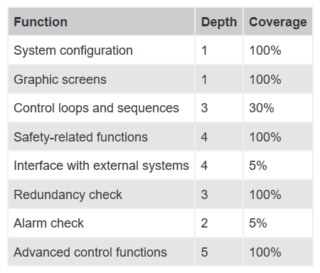 Table 2. Example of FAT specification
Evaluation of a PCS
Evaluating a PCS (and everything else) requires a quantitative procedure for identifying the requirements to evaluate, setting the importance of each requirement, and assessing a vote to the proposed solutions.
IEC 62603-1 suggests that the engineer/end user indicates the importance of each requirement with a heuristic "weight" ranging from:
- A, this requirement must be implemented
- B, this requirement should be implemented
- C, this requirement would help
- D, this requirement is optional
These weights set the importance of each requirement for the specific application. Each vendor may rate his or her proposal with a similar voting system:
- 0, the PCS does not meet this requirement
- 1, this requirement can be created or applied
- 2, the PCS meets this requirement
- 3, this requirement is native
When several bids are received, the engineer/end user can collect the results as shown in table 3 and calculate the vote of each bid with a simple weighted average:
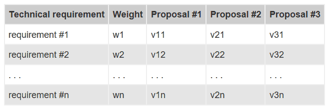 Table 3. Weights and votes table for bid comparison
The user can set a minimum acceptance threshold for some specific requirements. For example, requirements with weight A or B must obtain at least a vote of 2 to be accepted, and so on. When a function has a vote of 1 (it does not exist, but it can be created), it is convenient to add the cost for creating this function. Obviously, weights and votes are specific for the considered plant.
Conclusions
IEC 62603-1 is intended as a useful guideline for engineers, end users, makers, and system integrators for specifying, comparing, and testing process control systems. The standard defines all the requirements and functions that should be specified to identify a control system that matches the needs of a given process. In the future, 62603-2 will define the testing procedures for the factory acceptance test. IEC 62603 is fully integrated in the framework defined by the existing IEC standards for process control systems, and it represents an application of their inspiring principles. As of today, the procedures of IEC 62603-1 have been used by some end users and vendors with appreciation.
To emulate or simulate, that is the question
Very often emulation and simulation are used as synonyms, but there is a small difference worth highlighting. Emulation is the imitation of the behavior of an electronic system by means of another electronic system. For example, a PC with a given operating system may run software that emulates the behavior of another operating system. Simulation is the imitation of a real-word system or process by means of an artificial system. Simulators may be either based on mathematical models running on a computer or on analog systems that scale down the system to simulate or make use of physical analogies. Often, the simulator is a mix of digital and analog systems (like, for example, the rodeo bull simulators).
Testing a PCS may require an emulator for the I/O and a simulator for the logic. The emulator is physical for the hardwired I/O and software for the fieldbus links. A hardware emulator is traditionally a rack of switches for the digital inputs, 4–20 mA generators for the analog inputs, lamps for the digital outputs, and milliammeters for the analog outputs. These devices were previously controlled manually, but today are mainly controlled via a dedicated PLC. The size and the effort of wiring a hardware emulator may become very high. Emulating a fieldbus is a totally different story. Normally emulators are based on an interface card inserted in the motherboard of a PC or on a box with a USB port. This card or box implements the protocol of the fieldbus to emulate, and it guarantees the communication between the PC and the controller of the PCS under test (figure A1).
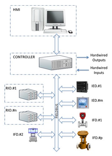 Figure A1. Typical architecture of a PCS with both conventional and fieldbus I/O
A specific program that runs on the PC emulates the remote I/O and/or the IEDs/IFDs connected to the fieldbus. According to the fieldbus used, each node is represented by a set of data grouped in a file with a specific structure and form. HART uses Device Description files; Profibus always uses GSD files and sometime FDT/DTM; Foundation Fieldbus uses both Device Description files and Capability files, just to cite only the most popular fieldbus for process control. Through the PC, the operator may force each variable manually using the software that controls the emulation card. The configuration of the emulator must match the configuration of the PCS, so that the data flow that the PCS will exchange with the field devices is fully recreated by the emulator.
Today process simulators are mostly based on a mathematical model that runs on a PC. Special software programs exist that use more or less standardized block languages to create the models of the components to simulate. The model runs in real time to create realistic feedback for the control logic implemented in the PCS. The interface between the simulator and the emulator is mostly based on OPC (figure A2). The process simulator calculates the dynamic behavior of the process variables that are transferred to the emulator via OPC. Similarly, the commands and the set points from the logic or the HMI of the PCS under test are transferred from the emulator to the process simulator. It reacts and sends the right feedback to close the loops. To make the simulation time shorter than the real process time, often engineers implement simplified models of the process. Process simulators are widely used by companies that produce specific products or processes. In these cases, the effort and the cost of implementing a process simulator is shared between many equal or similar applications. Customizing a process simulator for a given plant may become very expensive and time consuming, with the additional problem of validating the simulator (maybe with another simulator to validate, and so on).
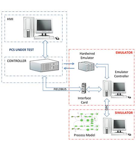 Figure A2. Interface between the PCS under test and the emulator/simulator
About the Authors
Paolo Pinceti, Ph.D., is a native of Genoa, Italy. He teaches measurement for industrial applications at the University of Genoa. His research interests include process automation, power system measurement, protection, and automation. Pinceti is the project leader of IEC TC65B WG6, which proposed the IEC 62603 standard.
Micaela Caserza Magro, Ph.D., was born in Genoa, Italy. She is currently with the University of Genoa, department DITEN, as a postdoc researcher. Her main research interests are industrial automation and communication. She is member of Profibus International and technical administrator of IEC TC65B WG6.
A version of this article also was published at InTech magazIne.


