This post overviews some of the benefits and methods of state-based control as it applies to the models defined by the ISA106, Procedure Automation for Continuous Process Operations standards development committee. It describes how procedure-based automation can enhance your adherence to alarm management best practices and coordination of safety instrumented functions
The problem
As continuous process industries have evolved, an increasing number of functions have been relegated to the basic process control systems (BPCS). Yet many engineers in the industry only leverage the full capabilities of the BPCS once the process has reached steady state (e.g., normal operation). The migration of the process through its transient states has frequently been managed manually.
Manual operation of the procedures during these transients often results in a plant that is more costly to run and maintain. If these tasks are not properly documented in standard operating procedures (SOPs), this methodology requires key personnel to carry out the procedures. The lack of documented procedures is exasperated by reductions of the workforce and the increasing median operator age, so much of this knowledge is being lost from the plant floor.
Consider a startup operation for a process. Even with well-documented procedures, operators may be required to manually apply bypasses and ignore extraneous alarms and some key performance indicators (KPIs), while paying close attention to others as they determine when it is appropriate to advance to the next step.
As a result, plant operation is often adversely affected. Costs increase due to:
- increased exposure to risks and hazards (reduced safety) in the process
- increased operator workload and reduced operator awareness
- increased losses and reduced product quality
- longer startups and shutdowns
- more trips
The solution
Applying the procedure-based automation methodologies set forth by ISA106 to the continuous process solves many of these problems by capturing knowledge frequently held by key personnel and identifying tasks to be executed, along with their initiating commands and rules for verification.
Many plants have written standard operating procedures. However, each operator must develop his or her understanding of the procedures when introduced to the system. This leads to inconsistent (or worse, incorrect) execution. Although the ISA106 technical report supports manual implementations, companies can achieve greater benefits by automating procedures.
If a procedure can be documented, it can be automated. Automated procedures help capture more detailed process knowledge, so operators can react more quickly to changing conditions in the process. This in turn leads to a more repeatable process, higher-grade products, quicker turnarounds, and reduced operator workloads..
To achieve an accurate representation of the application, the engineer must address all phases of the process. He or she needs to manage the coordination of the state the system is in and the tasks that are to be executed. This management is frequently referred to as “state-based control.” Applications within the continuous process industry have always had states that the plant, system, or process transitioned through on its way to the fully operational “production” state and back down to the “stopped” state.
A state is any well-defined phase in which a system can exist. The phase can be either categorized as “steady state” (e.g., distillation) or “transitional” (e.g., heating up), where a specific value (or values) is being controlled to a desired set point. Examples of states include stopped, ready to start, starting, production, stopping, and fault.
Unlike a typical sequence of a batch system that is executed and ultimately completed, a state-based control system is always in one (and only one) of its defined states at a time. At initialization (system reset), the system’s program is forced into the “stopped” state to ensure proper output commands (e.g., valves closed and pumps off). When the permissions are satisfied, the system goes to the “Ready_To_Start” state. When the StartCMD is received, the system leaves “Ready_To_Start” and goes to the “starting” state.
The system moves along the path through its states as the conditions of each transition are satisfied. These conditions include current state as well as KPIs and may additionally include operator acknowledgement or interaction. Program execution continues through the sequence until it returns back to “stopped” for another system cycle. The “transitional” states may be short lived with the plant spending most of its time in the production state, but it is essential to capture all the intermediate transitional states to complete the model.
The above example is a simplified circular loop and does not address any exception handling, such as trip conditions, abort commands, or emergency stops. State-based control typically has multiple branches where states can be entered from more than one adjacent state. Consider the following extended example (figure 2).
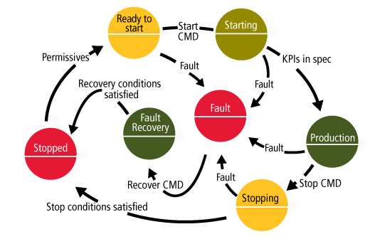
In this example, the normal execution is carried out along the outer loop. If a fault condition exists that warrants going to a special fault state, execution jumps to the “fault” state. The system “holds” here until the recovery command (RecoverCMD) is received. In the fault recovery step, the program executes steps that will prepare the system to be started again. This may include draining poor quality product to a waste tank, flushing a pipe, or coordinating with another system.
The result is that based on the state that the system is in, commands to initiate tasks and enable different trip conditions and drive final elements can be readily controlled. Additionally, operator displays can be decluttered and alarm flooding reduced through implementing ISA-18.2 Alarm Shelving based on the current state.
What is the ISA-106 technical report?
ISA-TR106.00.01-2013 – Procedure Automation for Continuous Process Operations – Models and Terminology was written to facilitate consistency of procedure-based automation within the continuous process industries. It specifies a set of terms, definitions, and models to be used as best practices in the design phase of the system’s life cycle. The technical report defines three models for categorizing and organizing the objects of the system: physical, procedure requirements, and procedural implementation (figure 3).
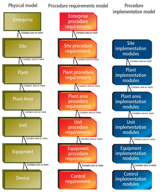
Physical model: The physical model maps the role-based equipment model functional levels 0 and 1 of ISA-95 into the continuous process. Each component in the model may contain zero or more subordinate components. The plant area might be the polymer section of the plant. Examples of units are a distillation column and a reactor; examples of devices are valve positioners and pumps.
Procedure requirements model: The procedure requirements model maps into ISA-95 functional level 2 and defines how the procedure requirements map into the hierarchy of the physical model. In the components of this model, it details what is required to accomplish an objective. An example of a unit procedure requirement is for a reactor to bring the temperature of its contents up to a prescribed temperature or perform a controlled shutdown during a process upset condition. An example of a control procedure requirement is turning on a pump or closing a valve.
Procedure implementation model: The procedure implementation model maps into ISA-95 functional level 2 and represents the configured or programmed result of the implemented procedure requirements. The linkage, mapping, and traceability of the implementation module to the requirements is not necessarily one to one. A requirement’s objective can be achieved by multiple implementation modules. Similarly, a single implementation module may satisfy multiple requirements.
Implementation modules contain at least one task and may contain composite tasks (tasks within a task). Each implementation module defines the command that initiates its execution, the steps required to be performed, and the detailed criteria to verify that the requirement result has been achieved or failed.
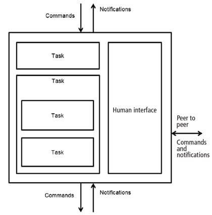 Example of implementation module block diagram
Commands, tasks, and verification can be implemented in a number of automation styles: manual, computer assisted, or fully automated. Consider a reactor agitation task that is to be started once the reactor contents are at temperature:
- Manual: The operator executes the command (e.g., pushing an AGITATE button to begin).
- Computer assisted: The operator receives a prompt from BPCS that the temperature is at the desired set point, and the operator acknowledges to allow the advance to the AGITATE step.
- Fully automated: BPCS automatically sequences to the AGITATE step once the temperature set point has been reached.
Use cases
Example 1: Conventional BPCS
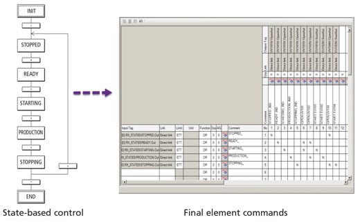
In a regulatory control BPCS, the implementation modules of the procedures can be managed by a state-based control engine developed in any of the languages available to the programmer. Typically, this is accomplished using a sequential function chart (SFC) that executes in a looping function, preventing the termination of the sequence. Each step of the SFC represents a state used to call its associated tasks. The tasks can be called directly, or the state can be forwarded to additional logic to control the final elements and monitor PVs. Tasks can be implemented as subsequent SFCs or control strategies.
Based on the indicated state, alarm functions can be coordinated to satisfy ISA-18.2 alarm shelving requirements.
Example 2: SIS with BPCS
In one recent implementation, the company needed to address the coordination of the chemical reaction between the BPCS and a safety instrumented system (SIS). The reaction is brought to the production state through a hazardous transient phase/state. The reaction is highly exothermic and requires a high-temperature trip condition for the “production” state. However, the “startup” state required a higher high-temperature trip and rate of change condition. The alarm management strategy also required the suppression of nuisance alarms on a per phase basis (e.g., low tank level alarms while filling during the startup state). Similar requirements existed for the “stopping” phase/state.
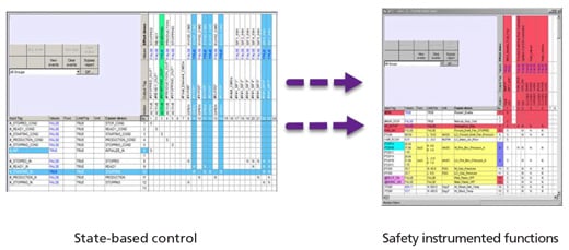
From the above requirements, certain trip conditions (safety instrumented functions [SIFs]) and alarms needed to be bypassed in some states and enabled in others. Because these SIFs were implemented in an SIS, the company needed to disable and enable the coordination of the state-based control in the SIS to protect the validity of the SIL calculations and compliance to ISA-84. The SIS provided this coordination and selectively disabled and enabled the associated SIFs based on phase.
The phase and state information was additionally communicated to the BPCS for its regulatory control of task requirements. With this technology, the engineer could automate the startup and shutdown of the system with confidence in a uniform response. Without it, the task to enable or disable bypasses of trips and alarms would rely on strict operator adherence to documented SOPs during high-stress conditions.
Benefits
The benefit of automating with state-based control in a continuous process is the reduced cost of plant operations. These cost reductions come in the form of risk reduction (improved safety), better product control, improved alarm management, reduced operator work load/fatigue, and improved visibility into plant asset management. The key benefits are:
- better safety (risk reduction)
- improved alarm management
- reduced operator work load
- maintenance planning with asset management
Improved safety is one of the key benefits of state-based control. The startup and shutdown operations of the continuous process are arguably the states when a dangerous demand to trip is most likely, yet these states are frequently manually monitored and controlled. Couple this with the high demands on the operators to achieve full operation, and mistakes are more likely to occur. If the trip conditions and their responses for the transient states are different from the operational state and can be well defined, they can be automated in the logic. Automating these reduces the operator work load and minimizes the chance of missed steps (e.g., removing a bypass when startup is complete) documented in the SOPs.
Alarm management is a critical issue in the industry, receiving much scrutiny at the corporate level. With state-based control, the alarms that are not appropriate during specific phases of the plant can be “hidden,” using alarm shelving techniques as defined in ANSI/ISA-18.2-2016, Management of Alarm Systems for the Process Industries. While alarms are hidden from the operator, they are still recorded in the journal system for completeness. The net result is operators are not distracted with nuisance alarms and can retain focus on the tasks they are charged with performing.
The automated nature of state-based control typically reduces the time-to-normal operation through infrequently executed states and grade changes. This type of control also generates higher quality products and achieves more repeatable production.
With state-based control, maintenance of the plants assets can be better predicted. Starting and stopping devices is typically harder on them than continuous operation. Having visibility into these demands allows scheduled maintenance, reducing unplanned plant downtime due to failures.
Control for all phases
The state-based control methodology of ISA-TR106.00.01 is an effective way to control a system during all phases of the system’s operation. It does require a shift in requirement documentation from the SOPs to the automation system. In the traditional methodology, the cost of defining these subordinate states, tasks, and requirements is often lost or buried in the development of the SOPs. There is no escaping it; they must be defined somewhere.
Bear in mind if the requirements can be documented, they can be automated in the controller’s program. The benefits of automating are a more repeatable system performance, safer systems, improved alarm management, and reduced operator workload.
A version of this article also was published at InTech magazine.


