One challenge faced by control systems integrators is the prospect of testing their software before deployment. Control systems integrators often work remotely, without having the actual equipment to manipulate, or even a full complement of I/O racks and modules. Programmable logic controller (PLC) software development may be done completely offline (static), or in a lab setting with only a PLC rack, a CPU, a power supply, and some kind of communications port. The control systems integrator often develops software in the lab and implements it in the field.
The vast majority of projects executed by control systems integrators are small, with a fast turnaround and limited budget, resources, and schedule. Although most modern PLC software has tools to simulate I/O, to force/clear internal bits, and to set analog values through animation tables, employing those techniques to perform a realistic test of the PLC program can be unwieldy and time consuming. In addition, from a validation point of view, the tests are not repeatable, as they depend on the user to input values and responses.
One alternative is to procure and configure simulation software to emulate field devices and complex control schemes. This software can be prohibitively expensive, requiring a very steep learning curve and having associated maintenance fees and recurring costs. To many, process simulation is simply a luxury.
Why simulate?
To our knowledge, no formal study has tested the actual time saved by making a software correction in the lab versus making that same correction in the field, but there is ample evidence to suggest those savings can be immense. This savings in time not only feeds the bottom line, but also mitigates the risk associated with a poor startup, which negatively affects prestige—a more important parameter than cost. This effect presents itself not only on huge process control projects with plentiful resources and visibility, but also on small tasks with minimal or no additional equipment or infrastructure. So, how can a control system integrator address the testing dilemma if the budget does not include a simulation software package?
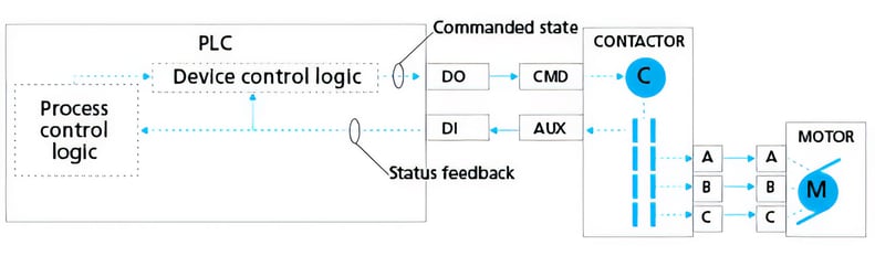 Figure 1. Typical motor control scheme
Passive loopback process simulation
Passive loopback process simulation (PLPS) is the answer. While ideally the PLC simulation will be on a separate PLC or PC that is communicating with the PLC under test, you can run the PLPS on the same PLC, with some restrictions, which we will discuss. It does not require any extra equipment or software packages. All it requires is a basic understanding of the external equipment and of how that equipment interacts with the PLC.
For most process applications, there is minimal need to simulate advanced control schemes. The primary goals are to simulate on/off for motors and open/close for valves, and cycle through sequences, demonstrate safety shutdowns, and then be able to demonstrate that the program reacts as it should to numerous upset scenarios.
Most programs resolve to two major sections: device control and process control. Device control logic supervises a specific field device, like a motor, and can have the following attributes:
- the output command to turn on a motor
- the interlock logic that will automatically shut off the motor in emergencies
- the permissive logic that, when in auto mode, will allow the motor to start/stop based on a set of conditions
- the timer that monitors the motor's auxiliary contacts to ensure the motor starts within a reasonable time limit
- the restart inhibit timer that prevents multiple restarts and gives the windings time to cool
- the motor run clock
- the auto/manual switching logic
- the remote/local switching logic
Other forms of device logic include (but are not limited to):
- on/off valves
- throttling valves
- variable frequency drives
- stepper motors
Process control logic is logic that is not specific to a device, but that controls the on/off, start/stop, speed, percent open/closed, and other values that drive one or more sections of device logic. Some examples of process control logic are:
- sequence logic that energizes/deenergizes and otherwise communicates with the device logic fragments to operate the field equipment sequentially
- proportional, integral, derivative ratio and other higher-level control algorithms
- combinational and supervisory logic that monitors multiple sensors and drives device logic in response to stimuli
In its most basic form, PLPS is all discrete (digital). The developer creates a simulation logic fragment for each PLC discrete output. Each fragment simply monitors the status of the software tag assigned to a physical discrete output and loops the signal back to a software tag associated with the physical discrete input that represents feedback from the field device. Injecting a short wait interval in this "loop back" will more accurately reflect the fact that a motor or valve has mechanical lags and so does not react instantaneously.
More advanced PLPS not only loops the discrete output back to its associated feedback discrete input, but also ramps any associated analog input signals to their normal operating values to simulate pressures or temperatures rising, or flows increasing, as the simulated equipment element does its job. Here are some basic rules for passive loopback simulation:
Simulation is only on inputs: Simulate discrete inputs and analog inputs only. The purpose of simulation is to control the things that stimulate the program, that cause it to react. This includes communicated variables and states, as well as discrete and analog signals attached physically to the system via I/O modules. No internal or external commands, operator (human-machine interface [HMI]) actions, or outputs are simulated. This allows the program to respond to external stimuli as it would in situ, providing a very valuable tool for both training and troubleshooting.
Simulation must be traceable: Any analog or discrete simulation tags must be easy to recognize, or all simulation needs to be in a single program section that you can delete before going live. In PLC systems where the inputs are located variables, the link to the physical I/O will need to be broken, either by deleting the physical address, or by some other means that tells the PLC to monitor the tag, and not the discrete input point itself. Each PLC system does this differently.
Simulation disabling: The things you are simulating must be able to be individually disabled, so that multiple failure modes can be simulated. For example, if a motor has five interlock signals, each should be individually accessible, so you can demonstrate that the motor stops if any one of the five interlocks is lost.
Simulation of higher-level control functions: Applying the same philosophy of simulating only the physical or communicated inputs is also valid for P&ID loops and other higher-level control functions. The controlled variable (CV) output is allowed to react as the process variable (PV) input is simulated or imposed.
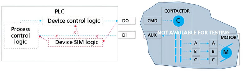 Figure 2. Simple motor simulation scheme
Practical example
If the end device associated with a particular output were a pump, then the simulator program fragment would have the following characteristics (may be replicated in ladder, function block, or structured text):
1. At start, simulate all associated inputs to be de-energized and cold: motor off, valves closed, flows at zero, temperatures and pressures ambient.
2. Monitor the discrete output, and when it goes “true,” do the following:
- Wait 0.5 seconds; set the “Aux Contact” to simulate motor start feedback.
- When “Aux Contact” is true, ramp temperatures, pressures, and flows associated with the pump to their normal levels. Do not continuously write those values, though, because some of the testing requires that the user be able to move the values around to see how things function. Consider putting those values on a test screen on the HMI, and give the user the rights to move those values around.
3. Monitor the discrete output, and when it goes “false,” do the following:
- Wait 0.5 seconds; clear the “Aux Contact” to simulate motor stop feedback.
- When “Aux Contact” is false, ramp temperatures, pressures, and flows associated with the pump back to their ambient levels.
Very simple. That is all there is to this logic fragment. It is common to have an HMI screen dedicated to simulation that gives the user the ability to enter analog values and inhibit simulation elements. At no time should any temporary simulation buttons on that HMI screen do anything other than enable/disable lines of simulation as described above. The pump program fragment might look something like this:
Initial conditions:
- Ensure the motor overload PUMP_OL discrete input simulates to indicate a normal state.
- Ensure any field switches (if discrete inputs are associated with them), are simulated to REMOTE (PLC Control)/AUTO operation.
SIMULATE PUMP10 START:
If PUMP10_OUTPUT then
Wait 0.5
If not(PUMP10_AUX_INHIBIT), then Set PUMP_AUX
Endif;
If PUMP_AUX then
If not(PUMP10_FLOW_INHIBIT), Set DISCH_FLOW = 10%
If not(PUMP10_PRESS_INHIBIT), Set DISCH_PRESS = 10%
Wait 1
If not(PUMP10_FLOW_INHIBIT), Set DISCH_FLOW = 50%
If not(PUMP10_PRESS_INHIBIT), Set DISCH_PRESS = 50%
Endif;
The various _INHIBITs listed above are all tied to HMI buttons that, when pressed, set the flag and prevent the action from taking place.
At this point, the pump is running, and process conditions are set to reflect that. Fluids are flowing, and pressure has risen to 50 percent of scale. Changing flow and pressure will cause the system to react. For example, a high-pressure interlock might shut down the pump. The user can now enter a high-pressure value and demonstrate that the software does in fact remove the PUMP_OUTPUT command.
SIMULATE PUMP10 STOP:
If not(PUMP10_OUTPUT) then
Wait 0.5
Clear PUMP10_AUX
Endif;
If not(PUMP10_AUX) then
Set DISCH_FLOW = 10%
Set DISCH_PRESS = 10%
Wait 1
Set DISCH_FLOW = 0%
Set DISCH_PRESS = 0%
Endif;
At this point, the pump has stopped, and process conditions reflect this with flow and pressure at zero.
Low-cost approximation
The purpose of a simulator is to approximate the behavior of external equipment, not to bypass or simulate internal logic. Passive loopback process simulation will provide a low-cost, first-order approximation of how the plant will react to the software. It will allow sequences to function, alarms to activate, and even high-level control functions like P&ID loops to operate. Operators can train on the system, because the simulator only reacts to the outputs that, in turn, only react to the main program or the operator, just as would actually happen. Simulating upsets by interrupting the feedback; by simulating high temperatures, pressures or flows; or by inhibiting interlocks and permissives, provides an effective, low-cost, and low-overhead training and software validation tool.
For Additional Reference:
Whitt, Michael D., Successful Instrumentation and Control Systems Design, Second Edition (with CD)
A version of this article also was published at InTech magazine.