

This post was authored by Fred Kohlmann, Midwest business manager for analytical products with Endress+Hauser
Water covers more than 70 percent of the earth’s surface and has varying degrees of purity in its natural form, ranging from crystal clear pure mountain spring water to highly saturated brine sea water. In the power generation industry, ultrapure water is used as a source to make steam to drive turbines and for other uses. Ultrapure water does not cause corrosion or lead to stress cracking in equipment such as turbine blades, stainless-steel lines, steam circuits, and cooling systems. Power companies use a great deal of ultrapure water, upward of 500,000 gallons per day for large plants. The ultrapure water can be processed from city water, a nearby river, or even seawater.
In most cases, the systems for producing ultrapure water are supplied by specialists in electrodionization, membrane, reverse osmosis, and other techniques for purifying water, and all require pH monitoring. Not only is pH monitoring required when the water is purified, it is also required as the water is used to maintain correct pH. The bottom line in power plants is that improperly conditioned water—based on a number of parameters, of which the main two are conductivity and pH—leads to corrosion and scale, which leads to inefficient operation and damage to vital parts. In the boiler, deposits cause heat transfer problems, reducing steam production capability. Corrosion from these deposits weakens the metal, leading to tube leaks that negatively impact the production of steam.
Large boilers, condensers, economizers, and superheater tube leaks can cause adjacent tubes to fail and are actually the largest cause of forced boiler shutdowns. The steam that passes through the turbine can cause deposits and corrosion from minerals, organics, and detergents that are present in plant water sources. Deposits on the turbines can cause pressure drops and unbalance the turbine, reducing speed and generation capacity. Unfortunately, conductivity measurement by itself does not provide enough water quality information for ultrapure water chemistry; therefore, pH must also be incorporated. Unless controlled, the effects of improper water treatment parameters will cause boiler tube failures and loss of efficiency due to coating of the tubes. This makes energy costs and ultimately operational costs higher. Boiler manufacturers have tight specifications on the minimum and maximum water quality parameters, pH being one of them.
Water’s tough
Water in its pure state is one of the most aggressive solvents. Known as the “universal solvent,” water, to one degree or another, will dissolve virtually everything to which it is exposed. Because pure water has a deficiency of ions, it looks for equilibrium with the ions it comes in contact with, and so it wants to strip these ions away from its host. For the purposes of this article, pure water is defined as having a conductivity between 0.055 to 10 microSiemens per centimeter (µS/cm), or 18.2 to 0.1 megohms-cm. Common manufacturer specifications for pH sensors can indicate a conductivity range of 10 µS/cm or greater. Herein lies the first hurdle to best measurement practices: to find pH sensors that are specifically designed to measure water with conductivity less than 10 µS/cm. Fortunately, some pH sensors are able to measure down to 0.1 µS/cm, but these are specialized instruments and must be specified, installed, and maintained accordingly.
There is a deficiency of ions in pure water, and pH sensors have the reputation of being noisy when measuring pH in these low ionic strength solutions. In simple terms, the signal is noisy because the sensor is looking for ions to capture and measure and has a hard time finding them, causing the measured value to meander up and down the pH scale. Using two or more brand new pH sensors from the same manufacturer—even right after being freshly calibrated in 7 and 4 pH buffers—the sensors may show differing values due to static charges and reference junction potential errors. Pure water is a poor conductor of electricity, and so static charges are an issue as water flows through the piping systems, requiring extra care in proper grounding for signal stability and noise rejection.
Also, extraneous electromagnetic interference (EMI) and radio frequency interference (RFI) can disturb the sensor’s electrical circuitry, especially in a power plant with high-voltage equipment. Walkie-talkie transmissions and electric motors or valves being cycled on and off can also create electrical noise. These interferences cause signal spikes that push the pH signal high or low for brief moments or freeze the signal in place. The pH sensors use a two-electrode scheme as the measurement apparatus—an active or measuring electrode and a reference electrode. The active electrode can have an input impedance of 100 megohms in high ionic strength solutions such as a pH 7 buffer. So in the best of circumstances, pH measurement has at least a 100 megohm obstacle to overcome. If that same impedance is added to the very low ionic strength of ultrapure water, it adds measurement complexity. There is now a larger resistance for the signal to traverse through the low ionic solution. The reference junction serves as the return or ground path for the pH measurement.
Any shifting of the electrical resistance in the reference path will change the overall resistance of the measurement and cause a shift in pH reading. This equates to a noisy signal. A charge buildup at the reference junction can change as the process changes (e.g., when valves or pumps are cycled) or remain at a constant state and attenuate the pH signal. If any air is introduced into the piping system of the pH sensor, it will add CO2 into the solution, which acidifies the actual pH value. Therefore, closed loop systems are needed for a constant and uniform measurement.
Consider the practice of taking a grab sample from a closed loop system for pH analysis. When one walks the sample back to the chemistry lab for analysis, what happens to the sample as it is exposed to the atmosphere? It likely changes, sometimes substantially, leading to a preference for in situ sensors. Changes in the flow rate past a sensor can also lead to changes in the pH measurement. These changes are referred to as streaming current potentials. Changes in process flows cause changes in the reference junction potential and lessen the ability of the glass electrode to maintain its hydrated outer gel layer. Problems can occur in pH sensor cable connections, terminal strips, and plugs.
Connectors can become loose or corroded or have moisture accumulate across the connections. These situations change the resistance of the pH measurement and degrade the signal. Long runs of cables without the aid of preamplification or signal conversion from analog to digital can lead to changes in the capacitance and resistance of the cable, which can affect the pH readings. Signal cables are also a means by which EMI and RFI can gain access to the transmitter circuitry, also causing measurement errors. Here are best practices for installing and maintaining pH sensors:
- Make the pH measurement in a sealed piping system
- Maintain a slow continuous flow rate past the pH sensor, about 100 mL/min
- Use conductive piping and fittings; 316 SS is common practice
- Keep cable runs as short as possible
- Maintain tight, dry, and corrosion-free electrical sensor connections
- Store unused pH sensors in a solution to maintain hydration: 4 or 7 pH buffer
- Use digital pH sensors instead of analog
Inside pH sensors
Many manufacturers offer pH sensors designed specifically for measuring pH in low ionic fluids of 10 µS/cm or less. Low-resistance glass and double and triple reference junctions, as well as flowing reference junctions, are employed with high degrees of success. Ceramic junction materials tend to have less “memory” and facilitate fast response times. The pH sensors using a flowing junction reference system (figure 1) tend to be more accurate as they minimize junction potentials, but they also require more maintenance. These types of systems use a reservoir of potassium chloride (KCl) solution pumped through the sensor’s reference element, and use either gravity or compressed air to maintain a constant overpressure as compared to the process being measured.
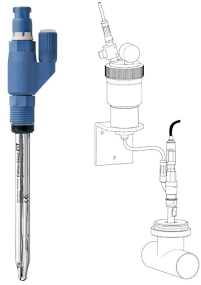 Figure 1. Flowing reference pH sensor with reservoir
Process fluid will eventually find its way through the junction and into the filling solution of the reference electrode. When this happens, it dilutes the KCl inhabiting this physical space. This dilution of the KCl will eventually lead to a change in the reference chemistry and to measurement inaccuracies. Flowing reference-style sensors deliver a fresh KCl solution through the junction and provide a constant nonchanging electrical reference path. These sensors also deliver a pH reading much faster than traditional sealed reference electrodes. Sealed reference-type pH sensors employ salt rings or circular pinhead-type reference junctions. Salt ring–type junctions may employ gelled KCl solutions to maximize the junction surface area and keep KCl flow at an optimum rate. Some of these sensor styles may also use an internally charged or pressurized reference.
Because these sensor types are considered closed systems, they have no reservoir to maintain, and the entire sensor is replaced as its reference becomes contaminated or as the solution within the reference gets depleted or becomes unusable. Temperature compensation of the pH signal is very important to accurately measure the pH of ultrapure water (figure 2). An entire paper discussing this subject could be written, but is not within the scope of this article. As temperature changes, so does the pH sensor’s millivolt output. Specifically, the electrode produces more millivolts/pH as the temperature increases, and as the pH goes farther in either direction from 7 pH. This change is predictable and linear, and can be compensated for in the pH analyzer by using the Nernst equation in the circuit design.
 Figure 2. Temperature as it relates to pH
The Nernst equation (figure 3) is a general mathematical equation that describes and predicts the pH electrode’s output based on a number of constant factors and just one variable, temperature.
 Figure 3. Nernst equation showing breakout of potentials and slope
Modern pH measurement systems incorporating temperature-compensated pH sensors are the norm. Avoid any pH sensor that comes without an integral temperature element or a transmitter that only accepts a manual or fixed temperature compensation network. A fast acting/responding temperature element should be mounted in the bulb of the pH sensor for best results.
Electrical considerations
Cables for pH sensors must be kept as short as possible, less than 10 feet without some type of preamplification or signal conversion. Furthermore, sensors should employ gold connections and O-ring sealed connectors, or use a digital inductively coupled sensor-to-cable connection to avoid EMI/RFI intrusions and moisture and corrosion problems. There are sensors (figure 4) that convert the pH signal from an analog to a digital value at the sensor and send this digital signal up to 300 feet from the sensor to the transmitter. These digital pH sensors are available from several vendors. Most are not affected by moisture or contamination of connectors.
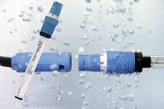 Figure 4. pH sensors convert the pH signal from an analog to a digital value at the sensor, and send this digital signal up to 300 feet from the sensor to the transmitter.
When using analog-type pH sensors, a common problem is a ground loop. A ground loop is a difference in the ground potential that the pH sensor sees versus the ground potential of the pH transmitter. Ground loops can be a constant or varying offset of voltage to the pH reading (leading to an inaccurate pH value). They can also be an on/off type signal that falsely increases or decreases the pH signal to the transmitter when an electrical device using the same ground is either turned on or off. Ground loops can be hard to find and tougher still to eliminate, but using inductively coupled digital pH sensors eliminates ground loop problems.
Calibration
Calibrations of pH sensors should be conducted regularly. This can be done during a process shutdown or by simply replacing the sensor with a calibrated unit. The use of the proper buffer solutions is a must, as calibrations need to be made in pH 7 and 4 buffers, never pH 10. Also, properly rinsing and drying the sensor between buffer immersions is critical for accuracy. It is also important to ensure the glassware and other equipment interfacing with the buffer and sensor are clean and free of contamination.
Calibrations should be made in accordance with the manufacturer’s recommendations, and proper care should be taken when cleaning the pH sensor. If large step changes in buffer readings occur from the previous calibration, the sensor is suspect and has either been damaged or contaminated. It should be cleaned properly to get the calibration closer to the last values. Large shifts in calibration values are not normal in ultrapure water chemistries. Digital pH sensors allow calibration in the laboratory or shop with either a separate transmitter, an alternate channel on a multichannel instrument, or hardware/software that allows hardware to directly connect to a PC.
With digital pH sensors, spare precalibrated sensors can rotate in and out of the process as needed. Calibration in this manner allows for longer and more accurate aging of the sensors in the calibration buffers. Also, a technician is not under pressure to have calibrations done on site while the system is down awaiting calibration completion and reinstallation of the sensor. This scenario is not possible with analog-type pH sensors, which is another advantage of digital pH sensors. Calibrated pH sensors not in use should be stored in a 7 pH buffer or 3 molar KCl solution. A pH sensor should not be allowed to go dry, either in the process or during storage.
If left to become dehydrated, the glass electrode will show higher electrical impedance from the norm and will react much more slowly to pH changes. It may take from a few minutes to hours or even days for the sensor to regain its original operational performance, if ever. Repeated cycles of hydration and dehydration significantly shorten the pH sensor’s useful life. The reference electrode is also affected by dehydration. If left dry, salt from the internal KCl fill solution will form salt crystals and cake the outer surface of the junction. Ultimately the junction may siphon out all its fill solution. Companies should premount and plumb pH sensors in stainless-steel flow loops (figure 5), where they are easily accessible for service and maintenance and where flow rates can be easily controlled.
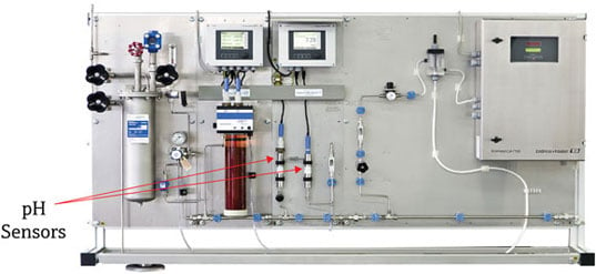 Figure 5. pH sensor installation in prefabricated panel
Sensors send signals to pH transmitters, which present the information to the control system. The transmitter should be easy to use; for example, just a few keypad manipulations should be sufficient to perform calibrations without having to use the instruction manual each time a calibration is performed. The transmitter should also provide sensor diagnostics to alert the user to the sensor state and deploy alarms or warnings should the sensor start to deviate from configured parameters. Modern transmitters can have virtually any desired output from 4–20 mA to relay/alarm contacts to multiple digital communication outputs such as HART, FOUNDATION Fieldbus, Profibus PA, or EtherNet/IP. Many pH transmitters have an integrated Web server, allowing remote users to access the transmitter from any Web browser.
Conclusion
Work with the manufacturer to select the best pH sensor for your application. If possible, look for the latest in technology for both the sensor style (junction and glass formulation) and the sensor’s signal transmission methodology (i.e., analog vs. digital). Usually, no two sensors within a single manufacturer’s portfolio can realistically serve the same application. There can be big differences in sensor design/construction for a sensor that is used in 10 µS/cm service as compared to a sensor designed for 1.0 to 2.0 µS/cm service. Make sure pH sensor cables and connectors are specified correctly for the distances involved and the environment in which they will be used, and keep them free of moisture and corrosion.
Pay attention to the materials used to mount the pH sensor and to the importance of stability in the flow rates past the sensor. Make sure the sensor is easily accessible for calibration and general maintenance. Make sure trained resources are available to maintain the pH sensors (cleaning and calibration) at the manufacturer’s suggested intervals. If these steps are followed, accurate and repeatable pH measurements can be made in ultrapure water, leading to improved operations, reduced maintenance, and increased uptime.
About the Author
Fred Kohlmann is Midwest business manager for analytical products with Endress+Hauser. Since 1976, he has been involved in engineering, design service, marketing, and sales of online analytical water quality and process control instrumentation.
Connect with Fred![]()
A version of this article also was published at InTech magazine.
