

This guest blog post was authored by Rob Iten, director of marketing at Comtrol Corporation. Rob has worked in the factory automation industry for more than 20 years.
IO-Link is a powerful yet simple protocol with wide industry support. IO-Link improves digital or analog sensor interfaces, providing significantly more information, configurability, and control to simplify installation, operation, and maintenance of an automation system.
IO-Link is being used in a wide range of applications as an open standard for smart sensor I/O—primarily for discrete devices. IO-Link is a point-to-point network communications standard and protocol that is an IEC standard (IEC 61131-9) for sensors and actuators. It has many advantages over hardwired I/O. IO-Link is thus not a fieldbus, but rather an evolution of the sensor/actuator connection to controllers. IO-Link lets smart sensors communicate information, including status, events, and configuration parameters to systems.
The IO-Link organization describes its goal as “bridging the last meter” to intelligent sensors and actuators. In 2006, work on the specification of the IO-Link standard began with just 21 companies. This led to the publication of the IEC 61131-9, single-drop digital communication interface (SDCI) for small sensors and actuators, standard in 2013. IO-Link was launched in 2009 with 41 member companies committed to the protocol. IO-Link has been growing at a fast rate, with more than 100 member companies in the IO-Link organization. Illustrating adoption, the organization references a notarized analysis that the number of IO-Link nodes in the field at more than 3 million.
IO-Link is managed by an open consortium of manufacturers and is currently an established technical committee (TC6) within PROFIBUS and PROFINET International. Working groups in the areas of technology, marketing, network integration, and profiles make up the infrastructure for further technical development and efficient dissemination of IO-Link technology.
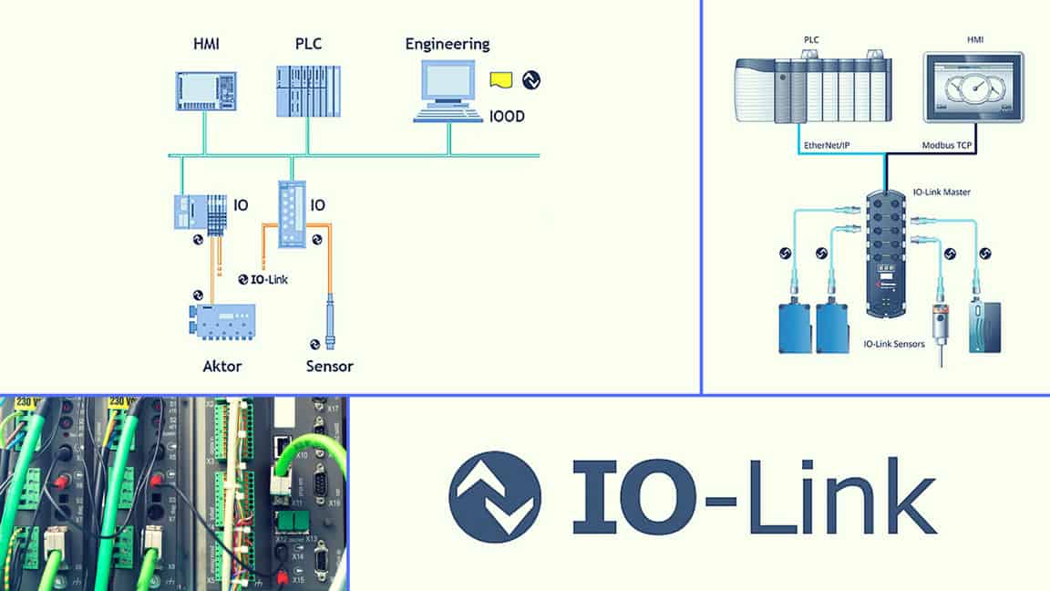
IO-Link
The advantages of IO-Link technology include simplified installation, automated parameter assignment, and expanded diagnostics. Due to low implementation and component costs, an IO-Link interface can be integrated even in price-sensitive field devices such as photoelectric sensors. IO-Link interfaces are available for a wide range of fieldbus systems on the market, including Profibus, Profinet, AS-i, CANopen, CC-Link, DeviceNet, EtherCAT, EtherNet/IP, Interbus-S, Powerlink, and Sercos III. The technology is undergoing consistent further development.
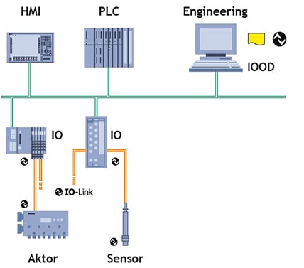 Example of IO-Link system architecture
Connection and power
An IO-Link system consists of IO-Link devices, including sensors and actuators and a master device. Because IO-Link is a point-to-point architecture, only one device can be connected to each port on the master. Each port of an IO-Link master can process binary switching signals and analog values (e.g., 8 bits, 12 bits, 16 bits). Serial IO-Link communication takes place via the same port. The connection between the IO-Link master and device is accomplished with an unscreened cable (maximum length 20 meters) that includes power for devices. IO-Link uses standard M5, M8, and M12 connectors, with the vast majority of IO-Link devices equipped with M12 connectors, which can be used without any restrictions for IO-Link’s switching mode and communication mode. Twenty-four-volt power up to 200 mA is supplied to devices through the cable. An IO-Link master can take many forms, such as a card in a programmable logic controller (PLC) rack or a standalone device that interfaces to standard fieldbus communications. For example, there are IO-Link proxies available for Profibus and Profinet. The association ODVA has an IO-Link special interest group for a single-drop digital communication interface for IEC 61131-9.
Logical connection
IO-Link is a serial point-to-point communication connection between two devices, typically at transmission rates of 4.8 kbaud and 38.4 kbaud. Examples of IO-Link smart devices include I/O blocks, valve bank connectors, measurement sensors, color sensors, and radio frequency identification (RFID) readers. At first, connection devices are always in the standard I/O (SIO) mode, and the master acts on this port like a normal digital I/O. If the port is set to communication mode, the master tries to find the connected IOLink device to initiate a wake up. During wake up, the master sends a defined signal and waits for the response from the device. The master tries to do this with the highest defined baud rate. If this is unsuccessful, the master tries the next lower baud rate. With every baud rate, the master tries to address the device three times. If the master receives a response (i.e., the device was woken up), both will start communication.
The first communication with a device is an exchange of communication parameters, and subsequent communication are exchanges of cyclic process data. If the device is removed during operation, the master detects the communication abort and reports it. The master communicates cyclically to wake up the device when it returns to service. After a successful wake up, the communication parameters will be again validated, and cyclic data exchange will be started. If the master terminates communication, both the master and the device return to the original mode—the SIO mode also known as fall back.
IO-Link device profile
Each IO-Link device has an IO device description (IODD) that specifies the data structure, data contents, and basic functionality—providing a uniform description and access for software and controllers. The user can easily read and process this information, and each device can be unambiguously identified via the IODD as well as via an internal device ID. When using devices from different manufacturers, users (e.g., mechanical engineering) can be sure that the specified functions are always available. Information includes:
Process data
This input or output data shows the latest state of the sensor or communicates the desired state of the actuator. It is communicated every communication cycle (usually about 2 ms) and can contain between 1 bit and 32 bytes of information.
Service data
Service protocol data units (SPDUs) allow the user to retrieve detailed information about the device. Communicated using up to 16,000 blocks, it can convey everything from basic device information (e.g., versions, type, serial numbers) to much more advanced information (e.g., configuration, detailed diagnostics, or status). Some parts of the information are standard to the protocol, but device manufacturers can make available any necessary information or configuration.
Events
Events that occur too rarely to be included in the process data, but should be reported without waiting for an SPDU to be queried, can be delivered using IO-Link’s event facility. This allows standard or vendor-specific information about any alarms or informational messages to be delivered as they are encountered.
Device replacement
IO-Link allows easy replacement of end devices. The master downloads parameters into the replacement device, which simplifies maintenance tasks. No additional configuration is required. Available IO-Link sensors include binary sensors, measurement sensors, photoelectric sensors, RFID readers, laser distance sensors, and color sensors.
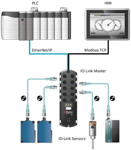 IO-Link sensors are wired directly to controllers or through gateways. There are four devices connected to a high-density IO-Link master industrial gateway interfacing to EtherNet/IP and Modbus TCP networks.
Protocol details
As a standard, 2 bytes of process data are available per cycle. The transmission between an IO-Link master and a device takes 400 µs at a speed of 230 kbaud. The user can also choose larger frame types up to 32-bytes length that can also be transmitted at a correspondingly lower cycle time. To ensure that the parameter data of a device is not lost when replacing a device, it can be automatically stored directly in the IO-Link master. If a new, identical substitution device is connected, the parameters of the previous device are automatically transferred onto the new device.
Quality of service
If communication fails, the master’s request is repeated twice. Only when the second attempt to send data fails will the master detect a communication abort and report it to the higher-level control system. The master measures the quality of the transmission (quality of service) with the number of telegram retries.
Data types
The IO-Link protocol supports various types of data—cyclic data (process data), acyclic data, service data, and events. The IO-Link device sends data only after a request from the IO-Link master. Acyclic data and events are requested explicitly by the master, and cyclic data is sent after the IDLE telegram of the master.
IODD
The IODD is an electronic data definition that is one or several XML files describing the device, manufacturer-specific properties, and image files in the PNG format. According to the IO-Link organization, this information can be easily read and processed by the user because it is in XML format.
Gateway
The IO-Link master provides a gateway function to exchange data between an IO-Link device and a PLC by mapping. If the IO-Link master is directly connected with a PLC over a proprietary backplane bus, the IO-Link data is mapped to this bus and transmitted to the PLC or from the PLC to the IO-Link master. IO-Link maps have already been specified for Profibus, Profinet, Interbus, AS-I, and EtherCAT.
Operations efficiency
There are a number of advantage to using IO-Link field devices, including:
Installation and commissioning
Whether installing a new system or retrofitting an existing one, IO-Link makes installing and commissioning a system much less demanding than traditional machine installations. Standard connectors and cables reduce wiring complexity by eliminating the need for custom cables, connectors, or termination. IO-Link’s parameterization simplifies new sensor configuration through standardized interfaces.
Operating efficiency
IO-Link’s ability to identify devices and provide access to the devices’ parameters gives you much more control than is offered by legacy sensors and actuators. Because re-parameterization can be automated, downtime associated with manually reconfiguring production can also be reduced or eliminated.
Maintaining a system
IO-Link provides information needed to maintain and maximize productivity on an automation network. IO-Link events help pinpoint issues and potential process errors before they occur. For example, a sensor might automatically send a notification to a PLC that its batteries are running low, allowing maintenance and avoiding machine downtime.
CPG manufacturer IO-Link application
A consumer packaged goods (CPG) manufacturer that produces several varieties of one product, requiring different printed labels during packaging, applied IO-Link to improve operations. The packaging is mostly automated due to the heavy machinery that is used and the high volume of product being packaged. The label printing occurs in the middle of the packaging cycle. Due to safety regulations, the area is blocked off during production. If configuration of a specific luminosity sensor for different printing requirements is needed during the packaging process, a technician is required to turn off all the equipment between production runs to access the luminosity sensor for reconfiguration. This required the technician to go through all the safety access points on the assembly line before reaching the sensor, and the downtime costs the company time and money. In addition, a long screwdriver has to be used to bypass the required safety barrier. This action is not just inconvenient and clumsy, but dangerous for the technician.
As well as changing the configuration method of the luminosity sensor, the company wanted to gain easy access to process data from a photoelectric sensor from a different manufacturer. This sensor detects the number of products coming off the line. It was a challenge for the company to make manufacturing adjustments in a timely fashion, as the data was hard to access and required additional PLC programs to be written.
In addition to remote configuration and accessing process data, the company also needed to easily integrate sensors from multiple manufacturers. In production, a variety of sensors were used to meet the specific needs of each system. Having a multitude of manufacturers’ sensors made installation, maintenance, and monitoring cumbersome. The company was seeking to increase efficiency by using a central management system for all sensors.
The company realized that the IO-Link standard provided the advanced capabilities required and would be simple to install in the existing architecture. The company had purchased IO-Link-enabled sensors and selected a master gateway to network them together that included features that made deployment easy:
Small form factor
Slim-line form factor makes it easy to mount to any machine, wall, or panel with M12 connectors. It has IP67 rating for reliability in harsh environments.
Straightforward PLC integration
Free sample programs simplify integration into PLCs, including ControlLogix, CompactLogix, SLC 500, MicroLogix, and PLC5. A flexible and simplified interface eased PLC programming.
Remotely configured luminosity sensor
Users can remotely view and update configurations based on current production requirements, which helps manage sensors in isolated or hazardous areas. Remote parameterization can be done through a PLC, human-machine interface (HMI), PC, smartphone, or tablet. A web server interface provides automatic discovery and default configuration of known sensors and devices.
Access to photoelectric sensor process data
Advanced diagnostic data via PLC, HMI, PC, smartphone, or tablet supplies the user with timely production control. This process data can help detect potential repairs or adjustments needed on the line in advance to avoid costly downtimes.
Integrate multiple manufacturers’ sensors
For this company, each sensor requiring access was designed by a different manufacturer. The gateway is sensor neutral and accommodates the production environments with a mixed array of sensors regardless of the manufacturer.
About the Author Rob Iten is director of marketing at Comtrol Corporation and has worked in the factory automation industry for more than 20 years.
Connect with Rob:![]()
A version of this article also was published at InTech magazine.
