In the glass manufacturing industry, raw materials are heated to high temperatures until they turn into liquid. At this stage the molten glass is still very viscous, but can be poured into molds to create desired intermediary or final products. Eventually when it cools the molten glass reaches infinite viscosity and solidifies into the desired shape. Thus, temperature and viscosity in a liquid are inversely proportional.
A similar concept applies to industrial impulse lines used to measure differential pressure. The liquid in the main line might have a particular temperature and viscosity, and you might assume that the impulse line won’t clog as it isn’t getting blocked in the main line.
But this is not the case when we puncture this line to enable impulse lines to connect to measuring instruments.
When such fluid flows through impulse lines connected to a pressure measurement device, the operating temperature of fluid drops drastically.
Here’s the reason for the drop in temperature. Impulse lines are typically very small (approximately one-half inch). So for a liquid in such small outside diameter line, most of its surface is in contact with the wall of the pipe and there is a higher transfer of heat, which causes a significant drop in temperature.
Second, the impulse lines are dead legs, and this creates further temperature reduction as the same fluid in the impulse tube is radiating heat.
So depending upon the length of the impulse line we can infer that impulse lines lead to significant drops in fluid temperature compared to the main pipeline.
In a refinery application at one of my project sites, a pipeline had a particular liquid flowing through it. From this line a tapping (sensing line) had to be connected to a pilot relief valve.
The temperature of the pipeline was approximately 300°C but the pilot relief valve was not rated for such high temperatures. (The maximum operating temperature of a pilot valve body varies from vendor to vendor.)
I proposed using a cooling element between the tapping and pilot valve.
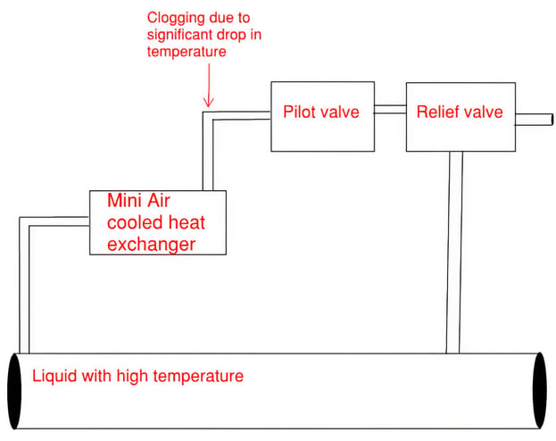
Refer the diagram below, which depicts an air-cooled heat exchanger configuration with pilot operated relief valve.
 Air-cooled heat exchanger with pilot operated relief valve.
The cooling element in the diagram is a miniature air-cooled heat exchanger. It was designed to lower the temperature close to ambient and protect the pilot relief valve. The cooling element would gradually reduce the fluid temperature to ambient conditions. This would lead to an increase in viscosity. After close examination it was determined that when the liquid temperature dropped below 40°C, it would become highly viscous and potentially block the impulse lines.
The pilot relief valve would not act due to the plugged impulse line and the valve - being the last line of defense - would not operate as required, possibly causing a catastrophic event. There have been several industrial accidents caused by such relief valve failures.
The solution was to heat trace the lines to 40°C to mitigate the liquid turning viscous and blocking the lines. So the key takeaway is to closely monitor the temperature of liquids in impulse lines, and always check the viscosity to ensure it is within acceptable operating limits.


