This post was written by Greg McMillan, industry consultant, author of numerous process control books, 2010 ISA Life Achievement Award recipient and retired Senior Fellow from Solutia Inc. (now Eastman Chemical).
Wireless measurements offer significant life-cycle cost savings by eliminating the installation, troubleshooting, and modification of wiring systems for new and relocated measurements. Some of the less recognized benefits are the eradication of EMI spikes from pump and agitator variable speed drives, the optimization of sensor location, and the demonstration of process control improvements. However, loss of transmission can result in process conditions outside of the normal operating range.
Large periodic and exception reporting settings to increase battery life can cause loop instability and limit cycles when using a traditional PID (proportional-integral-derivative) for control. Analyzers offer composition measurements key to a higher level of process control but often have a less-than-ideal reliability record, sample system, cycle time, and resolution or sensitivity limit. A modification of the integral and derivative mode calculations can inherently prevent PID response problems, simplify tuning requirements, and improve loop performance for wireless measurements and sampled analyzers.
Wireless measurements
The combination of periodic and exception reporting by wireless measurements can be quite effective. The use of a refresh time (maximum time between communications) enables the use of a larger exception setting (minimum change for communication). Correspondingly, the use of an exception setting enables a larger refresh time setting. The time delay between the communicated and actual change in process variable depends upon when the change occurs in the time interval between updates (sample time). Since the time interval between a measured and communicated value (latency) is normally negligible, on the average, the true change can be considered to have occurred in the middle of the sample time. This delay limits how quickly control action is taken to correct changes introduced by process disturbances.
Analytical measurements
Since ultimately what you often want to control is composition in a process stream, online analyzers can raise process performance to a new level. However, analyzers, such as chromatographs, have large sample transportation and processing time delays that contribute to the total loop deadtime and are generally not as reliable or as sensitive as the pressure, level, and temperature measurements.
The sample transportation delay from the process to the analyzer is the sample system volume divided by the sample flow rate. This delay can be five or more minutes when analyzers are grouped in an analyzer house. Once the sample arrives, the processing and analysis cycle time normally ranges from 10 to 30 minutes. The analysis result is available at the end of the cycle time. If you consider the change in the sample composition occurs in the middle of the cycle time and is not reported until the end of the next cycle time, the analysis delay is 1½ times the cycle time. This cycle time delay is added to the sample transportation delay, process deadtime, and final control element delay to get the total loop deadtime. The sum of the 1½ analyzer cycle time plus the sample transportation delay will be referred to as the sample time.
Smart PID
Most of the undesirable reaction to discontinuous measurement communication is the result of integral and derivative action in a traditional PID. Integral action will continue to drive the output to eliminate the last known offset from the setpoint even if the measurement information is old. Since the measurement is rarely exactly at the setpoint within the A/D and microprocessor resolution, the output is continually ramped by reset. The problem is particularly onerous if the current error is erroneous.
Derivative action will see any sudden change in a communicated measurement value as occurring all within the PID execution time. Thus, a change in the measurement causes a spike in the controller output. The spike is especially large for restoration of the signal after a loss in communication. The spike can hit the output limit opposite from the output limit driven to from integral action. The spike from large refresh time can also cause a significant spike, because the rate of change calculation uses the PID execution time.
A smart PID has been developed that makes an integral mode calculation only when there is a measurement update. The change in controller output from the proportional mode reaction to a measurement update is fed back through an exponential response calculation with a time constant equal to the reset time setting to provide an integral calculation via the external reset method. For applications where there is an output signal selection (e.g., override control) or where there is a slowly responding secondary loop or final control element, the change in an external reset signal can be used instead of the change in PID output for the input to exponential response calculation. The feedback of actual valve position as the external reset signal can prevent integral action from driving the PID output in response to a stuck valve. The use of a smart positioner provides the readback of actual position and drives the pneumatic output to the actuator to correct for the wrong position without the help of the process controller.
For a reset time set equal to the process time constant so the closed loop time constant is equal to the open loop time constant, the response of the integral mode of the smart PID matches the response of the process. This inherent compensation of process response simplifies controller tuning and stabilizes the loop. For single loops dominated by a large time in between updates (large sample time), whether due to wireless measurements or analyzers, the controller gain can be the inverse of the process gain.
In the smart PID, the time interval used for the derivative mode calculation is the elapsed time from the last measurement update. Upon the restoration of communication, derivative action considers the change to have occurred over the time duration of the communication failure. Similarly, the derivative response to a large sample time or exception setting spreads the measurement change over the entire elapsed time. The reaction to measurement noise is also attenuated. This smarter derivative calculation combined with the derivative mode filter eliminates spikes in the controller output.
The proportional mode is active during each execution of the PID module to provide an immediate response to setpoint changes. The module execution time is kept fast so the delay is negligible for a corrective change in the setpoint of a secondary loop or signal to a final control element. With a controller gain approximately equal to the inverse of the process gain, the step change in PID output puts the actual value of the process variable extremely close to the final value needed to match the setpoint. The delay in the correction is only the final control element delay and process deadtime. After the process variable changes, the change in the measured value is delayed by a factor of the measurement sample time. Consequently, the observed speed of response is not as fast as the true speed of process response, a common deception from measurements with large signal delay or lag times.
Communication failure
Communication failure is not just a concern for wireless measurements. Any measurement device can fail to sense or transmit a new value. For pH measurements, the broken glass electrode or broken wire will result in a 7 pH reading, the most common setpoint. The response of coated or aged electrodes and large air gaps in thermowells can be so slow to show no appreciable change. Plugged impulse lines and sample lines can result in no new information from pressure transmitters and analyzers. Digitally communicated measurements can fail to update due to bus or transmitter problems.
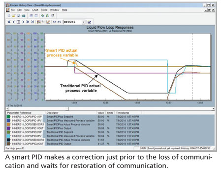
If a load upset occurs and is reported just before the last communication, integral action in the traditional controller drives the PID output to its low limit. The smart PID can make an output change that almost exactly corrects for the last reported load upset, since the controller gain is the inverse of the process gain.
Sample time
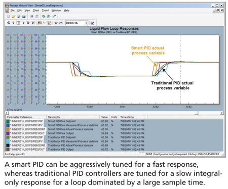
The wireless measurement sample time and transport delay associated with sample analyzers must be taken into account when using these measurements in control. A minimum wireless refresh time of 16 seconds is significant compared to the process response for flow, liquid pressure, desuperheater temperature, and static mixer composition and pH control. The sample time of chromatographs makes nearly all composition loops deadtime dominant except for industrial distillation columns and extremely large vessels. To eliminate excessive oscillations and valve travel caused by sample time and transport delay, a traditional PID controller is tuned for nearly an integral-only type of response by reducing the controller gain by a factor of 5. Increasing the reset time instead of reducing could also provide stability, but the offset is often unacceptable especially for flow feedforward and ratio control.
The smart PID can be aggressively tuned by setting the gain equal to the inverse of the process gain for deadtime dominant loops. The result is a dramatic reduction in integrated absolute error and rise time (time to reach setpoint). The immediate response of the smart PID is particularly advantageous for ratio control of feeds to wild flows and for cascade and model predictive control by higher level loops. The advantage may not be visible in the wireless or analyzer reported value because of the large measurement delay. The improvement in performance is observed in the speed and degree of correction by the controller output and reduced variability in upper level measurements and process quality. A similar deception also occurs for measurements with a large lag time relative to the true process response due to large signal filters and transmitter damping settings, and slow sensor response times. An understanding of these relationships and the temporary use of fast measurements can help realize and justify process control improvement. The ability to temporarily set a fast wakeup time and tight exception reporting for a portable wireless transmitter could lead to automation system upgrades.
Level loops on large volumes can use the largest refresh time of 60 seconds without any adverse affect because the integrating process gain is so slow (ramp rate is less than 1% per minute). Temperature loops on large vessels and columns can use an intermediate refresh time (30 seconds) and the maximum refresh time (60 seconds), respectively, because the process time constant is so large. However, gas and steam pressure control of volumes and headers will be adversely affected by a refresh time of 16 seconds because the integrating response ramp is so fast that the pressure can move outside of the control band (allowable control error) within the refresh time. Furnace draft pressure can ramp off scale in seconds. Highly exothermic reactors (polymerization reactors) can possibly run away if the largest refresh time of 60 seconds is used. To mitigate the effect of a large refresh time, the exception reporting setting is lowered to provide more frequent updates.
Measurement sensitivity
Measurements have a limit to the smallest detectable or reportable change in the process variable. If the entire change beyond threshold for detection is communicated, the limit is termed sensitivity. If a quantized or stepped change beyond the threshold is reported, the limit is termed resolution. Ideally, the resolution limit is less than the sensitivity limit. Often, these terms are used indiscriminately.
Wireless measurements have a sensitivity setting called deadband that is the minimum change in the measurement from the last value communicated that will trigger a communication when the sensor is awake. In the near future, the wakeup time in most wireless transmitters of 8 seconds is expected to be reduced. pH transmitters already have a wakeup time of only 1 second enabling a more effective use on static mixers.
A traditional PID will develop a limit cycle whose amplitude is the sensitivity and resolution limit, whichever is larger, from integral action. The period of the limit cycle will increase as the gain setting is reduced and the reset time is increased. A smart PID will inherently prevent the limit cycle.
Bottom line
Wireless and composition measurements offer a significant opportunity for optimizing process operation. A smart PID can dramatically improve the stability, reliability, and speed of response for wireless measurements and analyzers. The result is tighter control of the true process variables and longer battery and valve packing life.
A version of this article also was published at InTech magazine.