A common measurement in the oil & gas, chemical, and petrochemical industries is detecting the interface level between two liquids in the same tank or vessel, such as oil and water. The dissimilar density or specific gravity of the two liquids means the lower density liquid will float on top of the higher density liquid. In some cases, the two liquids will entirely separate, resulting in a "clear" interface that will be easier to detect.
In other cases, an emulsion or "rag" layer will exist between the two liquids. Other interface situations include multiple interfaces between more than two products, or the interface between a liquid and a solid. In some cases, it may be necessary to measure the thickness of the upper layer.
Why measure interfaces?
The reason for wanting to find the interface between crude oil and water in a refinery tank is obvious: A refinery does not want any water to enter the distillation process. Once a user knows where the interface is, he or she can separate off the top crude, leaving only the water to be processed separately.
Accuracy is very important here because any oil in the water means product losses, and any water in the oil requires extra processing. This is quite often the case with other products. A process may require separating two different products and not have one product contain remnants of the other. In some applications, the separation may not be quite as obvious, such as methanol in water, diesel and green diesel, black liquor and soap, and so on.
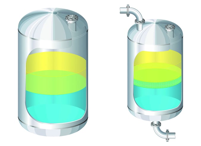
 Two basic kinds of level interfaces: a clear interface between two liquids (left) and an emulsion or "rag layer" between two liquids (right). Modern level measurement technology is capable of detecting all kinds of Interfaces, including multiple layers.
Why measure interfaces?
The reason for wanting to find the interface between crude oil and water in a refinery tank is obvious: A refinery does not want any water to enter the distillation process. Once a user knows where the interface is, he or she can separate off the top crude, leaving only the water to be processed separately.
Accuracy is very important here because any oil in the water means product losses, and any water in the oil requires extra processing. This is quite often the case with other products. A process may require separating two different products and not have one product contain remnants of the other. In some applications, the separation may not be quite as obvious, such as methanol in water, diesel and green diesel, black liquor and soap, and so on.
In most cases, the products are separating due to a difference in the specific gravity of the products. Even though this difference is enough to cause the product to separate, it may be too small of a difference on which to base an interface measurement. What variables are required to control the process? Is the overall level value needed as well as the interface? Does the operator need to know the thickness of the upper layer to prevent cross contamination of the separate products?
Level measurement sensors
No matter what the level interface application is, there are normally one or more level sensors that can solve it.
Floats and displacers: A float sensor does exactly what it sounds like-it floats on the top of the liquid. The float sensor can detect the level of the top liquid. To detect the interface, a displacer sensor that is calibrated to the specific gravity of the bottom fluid will float on the top of the lower or target fluid.
Displacer sensors are similar to float sensors; the difference is displacers are designed to operate completely submerged. Floats and displacers can be used to measure level interfaces of multiple fluids.
Floats and displacers are the simplest, least expensive way of determining level interfaces with a sensor, but they have two problems: First, they can only be used with the specific liquids for which they are calibrated; second, if turbulence exists in the tank, stilling wells for the sensors may have to be installed.
Another downside of using a float or displacer involves the mechanical float itself. If the product tends to coat or stick to the float, it will affect the weight of the float. Once the weight changes, then the float's ability to sit on top of one product may be affected. The same would hold true if the specific gravity of the product was to change.
Capacitance: A capacitance transmitter has a coated rod or cable that extends to the tank bottom and measures capacitance of material that is in contact with the sensor. The rod or cable of a capacitance transmitter acts like one plate of a capacitor, and the metallic tank wall acts as the other plate. Any material between the two plates changes the reading on the probe.
For a capacitance transmitter to measure the liquid interface, one of the products must be conductive and the other non-conductive. The influence of the conductive material on the sensor is what drives the reading, as the non-conductive material will have a very small effect on the output. One huge advantage of using capacitance in interface applications is it is not affected by emulsions or rag layers.
Like floats and displacers, a capacitance transmitter can have inaccuracies if the product changes or there is a change in the conductivity of the products. Capacitance will only give one output, and that will be the interface or the thickness of the conductive media according to how the unit is configured. Therefore, if a user wants the overall level and the interface, he or she will have to use two sensors and two different technologies.
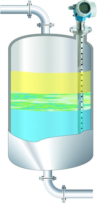
Guided Radar: A guided radar transmitter has a rod or cable that extends into the tank to "guide" the radar signal. Part of the radar energy will be reflected at the surface of the liquid and travel back to the transmitter. The time it takes the signal to go down and come back is proportional to the distance to the product. The remaining energy travels through the upper media, and it is reflected at the interface where there is a change in dielectric. Therefore it can give an output for the overall top level and the interface level.
It is unaffected by density and can detect the interface between two liquids as long as the dielectric constant (dk) between the two media is greater than 10 dk and any emulsion or rag layer is less than two inches thick. This technology does not function reliably in applications with thick rag layers. The upper media has to have a dielectric of less than 10 dk, or not enough of the radar signal can penetrate through it to read the interface.
Probes can be as long at 30 feet and are available in variety of materials. This will allow operation in severe conditions, including high or low temperatures and corrosive or abrasive materials. A guided wave transmitter is often ideal for use in the oil & gas and chemical industries.
Multi-parameter: One of the newest technologies in level interface measurement is a multi-parameter transmitter, which combines guided wave radar and a capacitance sensor on one coated rod or cable.
 Combining guided wave and capacitance technologies makes it especially suitable for measuring interfaces with emulsion layers.
The transmitter will normally use guided radar to make the interface measurement. If the emulsion layer gets too thick and the transmitter loses the guided wave reflection from the interface, it will automatically switch over to capacitance to make the measurement. The use of these two technologies eliminates many problems associated with interface level applications.
Capacitance is not affected by emulsion or rag layers in interface applications, and the guided radar allows the transmitter to monitor the overall level as well as the interface level. The transmitter has a multi-echo tracking algorithm that can track up to 20 tank echoes simultaneously as the tank level rises or lowers. This ensures the transmitter will not make a "jump" to an echo that is not the true level, such as an internal tank obstruction or heater coils.
 Gamma guages can be expensive, but they can solve level interface problems that baffle other sensors.
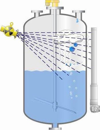
Gamma: Sometimes called a nuclear or radiometric sensor, a gamma-based system uses nuclear radiation to detect levels and interfaces. The source is mounted on one side of the tank and emits energy through the wall of the tank and process media. The radiation is measured by a detector or multiple detectors on the other side of the tank.
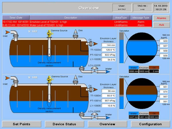
When used for interface measurement, the attenuation of the radiation energy is different as it passes through products with dissimilar densities. Multiple detectors are commonly used to locate an exact interface location and to identify multiple interfaces or layers. Software programs can convert the outputs from multiple detectors into graphical representations of multiple interfaces and emulsion layers. The graphics show the thickness and location of various layers.
 Software converts detector values into graphical images of level interfaces
Some of the vessels used in interface applications-such as oil/water separators-are too large in diameter for the gamma energy to penetrate all the way through the vessel. For these applications, the energy source can be inserted in a stilling well inside the vessel to reduce the distance the energy must travel.
Advantages of a gamma system include automatic compensation for temperature changes, as well as no affect from foam, gases, or corrosive materials. It is also non-invasive and maintenance free and can make multiphase measurements by using multiple detectors.
Disadvantages are the cost and the need to comply with the Nuclear Regulatory Commission and various state or country nuclear radiation rules and regulations.
Ultrasonic: Ultrasonic transmitters are used in solids/liquid interface applications. Here a user may be looking for the level of un-dissolved salt under a brine solution or the amount of sludge below the water in a settling basin in a wastewater plant. The ultrasonic transducer is mounted so it is submerged in the liquid at all times. The transducer sends an ultrasonic signal through the water or liquid, and the signal is reflected back to the transducer by the submerged solids level. This is much the same principle that a fish finder uses. This helps an operator maintain, control, or monitor the level of solids under a liquid.
Other solutions: The simplest solution is to use a sight glass mounted on the side of the tank or bypass assembly, and manually read the interface level. Engineers have also used differential pressure meters, bubble tubes, and magnetostrictive sensors-but floats, displacers, capacitance, guided wave radar, and gamma systems are most commonly used technologies for level interface measurements.
Selecting a sensor
No one sensor can solve all level interface measurement problems, but a user can often find more than one technology that can do the job. And, in some cases, two different level sensors can be used-such as an ultrasonic and capacitance transmitter-to measure the overall level and the interface.
The best advice is to consult with a local manufacturer's representative to learn what the best technology is for a particular application. Most process instrumentation vendors have provided sensors for countless level interface applications involving dozens of different liquids, and a representative can tap into this accumulated knowledge. The world's most advanced instrument will not work if it is installed in the wrong process or just not applied correctly.
A version of this article also was published at InTech magazine.


