

This post was authored by Ned Espy, technical director at Beamex.
The typical approach to calibration has been to regularly test instrumentation that affects successful control, safe operation, quality, or other relevant criteria. In most cases, scheduling is conservative, and methods at a particular site have evolved over time. Instrument technicians follow practices that were set up many years ago.
It is not uncommon to hear, “this is the way we have always done it.” Measurement technology continues to improve and is getting more accurate. It is also getting more complex—why test a fieldbus transmitter with the same approach as a pneumatic transmitter? Performing the standard five-point, up-down test does not always apply to today’s more sophisticated applications.
In general, calibration tasks require special skills and an investment in test equipment. Sophisticated, highly accurate, and multifunctional calibration equipment incorporating high-accuracy field calibrator and fieldbus communications for industrial networks (including HART, FOUNDATION Fieldbus, and Profibus PA instruments) is required to effectively calibrate advanced instrumentation, such as multivariable and smart/digital instruments. With the complexity of instrumentation, there is more pressure than ever on the calibration technician. Technicians with more than 30 years of experience at a single plant are retiring and cannot easily be replaced by outsourcing or by younger technicians. Documentation requirements are becoming much more common for improved quality, environmental monitoring, and government regulations adherence. Calibration software is often required to store and analyze detailed data as well as generate calibration certificates and reports. All of these factors should cause companies to scrutinize and evaluate current practices. Consider simpler and more efficient test methods to ensure proper plant operation.
While not a new concept, there are advanced calibration techniques based on loop testing. In some cases, it is the best practice to perform individual instrument calibration to achieve maximum accuracy (e.g., custody transfer metering). However, there are viable methods to test a loop end to end. If readings are within acceptable tolerances, there is no need to break into the loop for individual instrument testing. To be effective, a common-sense approach is required with the goal to minimize downtime and maximize technician efficiency while ensuring reliable control and maintaining a safe work environment.
Loop basics: What is a loop?
The idea of a loop can mean different things to different people based on their work background or industry. In practice, a loop is simply a group of instruments that in combination make a single measurement or affect a control action in a process plant. A typical temperature example is a temperature element (resistance temperature detector [RTD] or thermocouple [T/C]) that is connected to a transmitter, which is connected in series to a local indicator, and finally to a control system input card (distributed control system [DCS] or programmable logic controller [PLC]). The signal is then displayed on one or more control panels, and the measurement is ultimately used to control the process.
When evaluating a loop for testing, an important distinction is can the loop be tested from end to end or can only a portion of the loop be tested? For an end-to-end test, in the example temperature loop (figure 1), the temperature element needs to be removed from the process and placed in a dry block or temperature bath to simulate the process temperature. The final displayed measurement is compared to the simulated temperature, and the error interpreted. An end-to-end loop test is the best practice; if an accurate temperature is made for the control process, it does not matter how the individual instruments are performing. The DCS/PLC value is what is used to make any control changes, alarms, notifications, etc. However, if the loop measurement has a significant error, then the error of each instrument in the loop should be checked and corrected one by one to bring the final measurement back into good operation.
In some cases, it is not possible to make an end-to-end loop test. In the example loop, it may be extremely difficult or expensive to remove the probe from the process or to insert the probe into a temperature block or bath. If this is the situation, then a partial-loop test can be performed. The temperature element is disconnected from the transmitter, and a temperature calibrator is used to simulate a signal into the transmitter. As in the end-to-end loop test, the final displayed measurement is compared to the simulated temperature, and the error interpreted, etc. While the loop is broken apart, it would be good to check the installed temperature element; perhaps a single-point test could be done by temporarily inserting a certified probe or thermometer into the process and comparing that measurement against the element’s output when connected to a calibrator.
Analysis of loop error
Error limits can be somewhat difficult to determine, and many mistakes are made when it comes to setting them. One common judgment is to base process measurement tolerance on a manufacturer’s specification. Some manufacturers are better than others, but the marketing department might have as much to say about an accuracy specification as a research and development engineer. Furthermore, accuracy statements are generally off-the-shelf values that do not include such things as long-term stability (typically a significant error component), repeatability, and temperature effects. Sensor and transmitter accuracy should be a consideration of what the process measurement tolerance should be, not the final value.
The best method is to have a collaborative discussion between the control engineer, the quality or safety engineer, and the instrument engineer to set a realistic and practical tolerance. It is very important to keep in mind that the tighter the tolerance, potentially, the more expensive it will be to both make and maintain the measurement. The balance falls somewhere between the required tolerances to have efficient control, the best quality, and the highest safety versus minimizing downtime, maximizing technician efficiency, and utilizing optimum test equipment. In practice, it is common to see error evaluation as a percent of span. However, this does not easily apply to flow measurements (typically a percent of reading or rate) or analytical instruments (e.g., pH or parts per million).
One good way to look at error is to think in terms of the loop’s input engineering units. For the temperature loop example (figure 1), the discussion should focus on the minimum temperature error that creates the highest operating efficiency without compromising quality or safety and that can be realistically measured by the calibration or test equipment. One other complication for loop error is a given loop is no more accurate than the least accurate component contributing to the measurement. Today’s transmitters are extremely accurate and provide excellent performance; however, temperature sensors are typically not nearly as accurate and, depending on the process, can exhibit significant drift. If a typical RTD is rated to ±0.5ºF, a control engineer cannot expect better than ±0.5ºF to control the process. In reality, even though the transmitter and DCS analog-to-digital conversion can be significantly more accurate, recognize that these components add additional error to the loop measurement. A common practice to compute loop error is a statistical average or a root-mean-square (RMS) calculation. For the temperature loop example, assume the RTD sensor is rated ±0.5ºF, the transmitter is ±0.10 percent of span (span = 50ºF to 250ºF), and the DCS input card is ±0.25 percent of span (span = 50ºF to 250ºF). The loop error is:
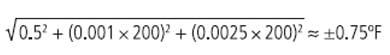
The most conservative approach is to simply sum the errors (0.5 + 0.2 + 0.5 or ±1.2ºF). The final decision should also take into account the criticality of the measurement along with the impact the error will have on the process and the risks involved.
The discussion should not end here. The control engineer will push for the lowest number possible (±0.75ºF), but there are other factors. An evaluation of the test equipment is required. The typical temperature block has an accuracy anywhere from 0.3ºF to 1.0ºF, and it is good practice to have a 4:1 ratio of test equipment versus process measurement. To make a proper temperature simulation, a reference probe (reference or secondary primary resistance thermometers) and an accurate primary resistance thermometer both need to be used to improve measurement error to 0.1ºF to 0.2ºF. This could impose a significant investment in test equipment, depending on the industry. Note the more accurate test equipment has a higher maintenance cost. For example, what if the quality engineer reports that an error of ±5ºF is all that is needed to make a good product? Why impose an unnecessary burden on the instrumentation department? If the control engineer has no objection (after receiving input from reliability, safety, etc.), a practical approach is to set a loop tolerance of ±2.0ºF, assuming the temperature block is accurate to ±0.5ºF over the range of 50ºF to 250ºF. Although not as accurate as the instrumentation in the loop, it is better than 2:1 for what is required to make a quality product and allows the calibration technician to use a simple combination of equipment.
Although this is just one scenario, it is a good practice to determine the “weakest link” in the loop and not set an unrealistic performance tolerance. When looking at fuel costs or process efficiencies, this type of analysis could easily justify a larger investment in test equipment and frequent testing if the cost or risk of error is high. With good judgment, companies can strike a balance and avoid unreasonable testing requests, meeting lean manufacturing objectives.
Loop testing examples
Temperature loop test example
If a process plant has hundreds of temperature loops like the example (figure 1), there are good benefits of loop testing. While it takes time to make a test with a temperature block, the calibration technician is effectively checking two, three, or more instruments that make up the loop. With this approach, it might make sense to invest in more rugged or more accurate probes to minimize failures. Depending on the process, more frequent testing may be required, but in any case, management will have a high level of confidence in the accuracy of the measurements. With repeatable work methods, technicians will recognize common issues, and there should be efficiency gains. If calibrations are documented, companies can analyze test cycles and extend or at least optimize the most likely intervals. There will always be a need for troubleshooting and emergency repairs, but the loop cycle should be reset whenever such an event occurs. This methodical approach effectively provides a “touch” to every instrument in the plant while minimizing disturbances to the loop integrity and delivering the very best measurements to the control system.
 Figure 1. Example temperature loop
Multivariable loop example
Flow measurements can be very demanding and often require very tight performance tolerances. In the case of natural gas metering or steam metering, a small error can cause significant errors in billing, creating extra scrutiny by management. A common example of orifice metering is to compensate for the differential pressure measurement by factoring in the process temperature and static pressure. The DCS can process these three measurements to make an accurate flow calculation. However, there are now differential pressure flowmeters (i.e., multivariable) with an integrated process RTD and static pressure measurement that have a compensated flow measurement output; the flow calculation is built into the smart transmitter (figure 2).
 Figure 2. Example multivariable loop
If the control system independently processes the three measurements, typical test procedures apply, but a loop test should be done to verify the accuracy of the compensated flow reading. Multivariable meters appear to be complex. However, by identifying the measurement components, a loop test can be set up to quickly verify that the meter is correctly measuring the flow to a desired percent of reading accuracy. For example, consider a steam application:
- Input pressure range: 0 – 250 inH2O
- RTD input range: –200ºF to +800ºF
- Normal process temperature: 450ºF
- Static pressure input range: 0 to 800 psi
- Ambient barometric pressure: 14.735 psia average local barometric pressure in 2012)
- Output: 4–20 mA (typical range of 0 –1500 lbs/hr, ±1 percent of reading)
For this example, set up a nonlinear test where the expected pounds per hour (lbs/hr) output is calculated for specific pressure input test points assuming a constant, typical 450ºF temperature and a static pressure of 14.735 pounds per square inch (psi), since the low side of the transmitter is vented to atmosphere for testing. Consulting with the control engineer, expected measurements might be:
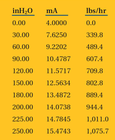
Instruments are available that have unique features for testing multivariable transmitters. The proceeding nonlinear table can be entered into software for a specific tag and can be downloaded into the test instrument for testing. Additionally, the three tests can be performed on the process variables versus each HART value that is used in the compensated output calculation. The only additional test tool required would be a temperature block. The loop test should simply be a five-point check of inches of water (inH2O) versus pounds per hour at 0 percent, 50 percent, 100 percent, 50 percent, and 0 percent. If all the measurements fall within 1 percent of reading, the technician can move on to the next instrument. If the loop test result is marginal or a failure, then three tests of the differential pressure versus HART, RTD temperature versus HART, and static pressure versus HART will need to be performed and adjusted as needed. Upon completion of the three variables that plug into the flow calculation, a quick check of the 4–20 milliampere (mA) output should be done as well. Assuming one or more of the inputs required adjustment, a final “as left” loop test of the improved flow output will document that the meter is in good operating condition. It saves time to focus on the nonlinear input versus flow output for a multivariable loop. This will result in a much simpler maintenance task for the instrument technician.
Other loop examples
A pressure loop can easily be checked by applying a pressure to the input transmitter and comparing it to the DCS or final control reading. This can be done very quickly and can be much more effective than testing just the transmitter. Any batch control loop should be evaluated for loop testing with the goal to make work more efficient for the technician while verifying that control measurements are as accurate as possible.
This same technique should be considered for control valve testing, where a mA input into the I/P is compared to a mA output (feedback). This would also apply to smart control valve positioners using a communicator to step the valve and monitor the digital feedback. By making 10 percent test points, a quick test on a valve will verify it is operating correctly. In most cases, the valve will pass, and the technician can make a quick round of testing critical control valves.
An overlooked component of a flow loop is the primary element (orifice plates, annubars, or averaging pitot tubes). These are critical for proper flow measurement. They cannot be calibrated, but they should be inspected for damage or wear.
Another critical area where loop testing should be considered is the safety instrumented system (SIS). When the process is down, it is common to follow a script of testing procedures that can include calibration of single instruments. However, whenever possible, consider checking an entire loop where the integrity of a critical measurement can be verified, especially for temperature (using a block or bath) or pressure measurements. Also, it may be possible to perform quick and simple tests on an SIS while the process is running to ensure systems are operating properly.
Calibration for optimum control
Many, many process plants perform calibration by simply checking the transmitter. It takes time to use a temperature block or bath, but consider how important it is to test all the devices that make a given measurement. Transmitters are not the only devices that drift. Temperature probes drift due to thermal stress/shock and vibration or physical damage. DCS and PLC input cards drift as much or more than transmitters. If loops are not being tested, how can a good measurement be made? Without good measurements, how can optimum control, safety, reliability, and quality be ensured?
As instrumentation and automation evolve, so should the methods for calibrating instrumentation. Loop testing is not a new concept, but it is underutilized for instrumentation testing as an effective strategy. New integrated calibration devices enable flexible tests that meet a variety of applications and provide detailed documentation and electronic reporting.
By approaching the task of calibration with a fresh look, there are plenty of opportunities to do more with less and effectively “touch” every instrument in the plant more efficiently using loop calibration strategies. Logical and careful planning of loop testing strategies results in improved control performance without compromising quality, reliability, or safety of plant operations.
Blog Posts
How Often Do Measurements Need to Be Calibrated?
Just in Time, or Just Too Late? A Kaizen Approach to Calibration
How to Improve Industrial Productivity with Loop Calibration
Temperature Calibration: Using a Dry Block to Calculate Total Uncertainty
How Can Advanced Calibration Strategies Improve Control Performance?
How to Calibrate a Pressure Transmitter
Webinar Recordings
Uncertainty in Calibration
Calibration Uncertainty and Why Technicians Need to Understand It
How to Avoid the Most Common Mistakes in Field Calibration
Learn Advanced Techniques in Field Calibration
How to Build an Industrial Calibration System Business Case
How to Use Calibration Tools for Accurate Process Temperature Measurement
How Does Low Flow Affect Differential Pressure Flowmeter Calibration?
Three Common Pitfalls of Pressure Calibration
How to Calibrate Differential Pressure Flowmeters
Free Downloads
ISA Industrial Calibration Worksheets
Measurement Uncertainty Analysis Excel template plus book excerpt
Calibration Handbook of Measuring Instruments book excerpt
In-Depth Guide to Calibration for the Process Industries eBook
Calibration Uncertainty for Non-Mathematicians white paper
About the Author
Ned Espy has been promoting calibration management with Beamex for more than 20 years. He has directed field experience in instrumentation measurement application for over 27 years. Today, Ned provides technical & application support to Beamex clients and partners throughout North America.
Connect with Ned![]()
A version of this article also was published at InTech magazine.
