The following technical discussion is part of an occasional series showcasing the ISA Mentor Program, authored by Greg McMillan, industry consultant, author of numerous process control books, 2010 ISA Life Achievement Award recipient and retired Senior Fellow from Solutia Inc. (now Eastman Chemical). Greg will be posting questions and responses from the ISA Mentor Program, with contributions from program participants.
In the ISA Mentor Program, I am providing guidance for extremely talented individuals from Argentina, Brazil, Malaysia, Mexico, Saudi Arabia, and the USA. This question comes from Daniel Brewer.
Daniel Brewer, one of our newest protégés, has over six years of industry experience as an I&E technician. He attended the University of Kansas process instrumentation and control online courses. Daniel's questions focus on aspects affecting thermocouple accuracy.
Daniel Brewer’s Question
How do you calibrate a thermocouple transmitter? How do you simulate a thermocouple? When do you use zero-degree reference junction? What if your measuring junction temperature varies?
Hunter Vegas’ Answer
Most people use a thermocouple simulator to calibrate temperature transmitters. You can usually set them to generate a wide selection of thermocouple types. Just make sure the thermocouple lead you use to connect the simulator to the transmitter is the right kind of wire.
“Calibrating” the thermocouple is another matter – because realistically it works or it doesn’t. You can pull it and put it in a bath though very few people actually do that. However if it is critical most will take the time to either put the thermocouple in a bath or dry block or at least cross check the reading against another thermocouple or some other means to check it.
The zero degree junction is a bit more complicated. Basically any time two dissimilar metals are connected a slight millivolt signal is generated. That is what a thermocouple is – two dissimilar metals welded together which generate varying voltages depending on the temperature at the junction. When you run a thermocouple circuit you try to use the same metals as the thermocouple for the whole circuit – that is you run thermocouple wire that matches the thermocouple and you use special thermocouple terminal blocks that are the same kind. This eliminates any extra junctions – the same metal is always connected to itself. However at some point you have to hook up to some kind of device that has copper terminal blocks – (transmitter, indicator, etc.). Unfortunately this creates another thermocouple junction where the copper touches the wires. That junction will impact the reading and will also fluctuate with temperature so the error will be variable.
To fix this most devices have a cold junction compensation circuit built in that automatically senses the temperature of the terminal block and subtracts the effect from the reading. Nearly every transmitter and read out device has it build in as a standard feature now – only older equipment would lack it.
Greg McMillan’s Answer
The error from properly calibrated smart temperature transmitter with the correct span is generally negligible compared to the noise and errors from the sensor and signal wiring and connections. The use of Class 1 special grade instead of Class 2 standard grade thermocouples and extension lead wires enables an accuracy that is 50% better. The use of thermocouple input cards instead of smart transmitters introduces large errors due to the large spans and inability to individualize the calibrations.
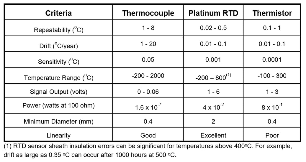
Thermocouple (TC) drift can vary from 1 to 20 degrees Fahrenheit per year and the repeatability can vary from 1 to 8 degrees Fahrenheit depending upon the TC type and application conditions. For critical operations demanding high accuracy, the frequency of sensor calibrations needed is problematic. While a dry block calibrator is faster than a wet batch and can cover a higher temperature range, the removal of the sensor from the process is disruptive to operations and the time required compared to a simple transmitter calibration is still considerable. The best bet is a single point temperature check to compensate for the offset due to drift and manufacturing tolerances.
Join the ISA Mentor Program
The ISA Mentor Program enables young professionals to access the wisdom and expertise of seasoned ISA members, and offers veteran ISA professionals the chance to share their wisdom and make a difference in someone’s career. Click this link to learn more about how you can join the ISA Mentor Program.
In a distillation column application, operations were perplexed and more than annoyed at the terrible column performance when the thermocouple was calibrated or replaced. It turns out operations had homed in on a temperature setpoint that had effectively compensated for the offset in the thermocouple measurement. Even after realizing the need for a new setpoint due to a more accurate thermocouple, it would take months to years to find the best setpoint.
Temperature is critical for column control because it is an inference of composition. It is also critical for reactor control because the reaction rate determining process capacity and selectivity setting process efficiency and product quality is greatly affected by temperature. In these applications where the operating temperature is below 400 degrees Fahrenheit, a resistance temperature detector (RTD) is a much better choice. Table 1 compares the performance of a thermocouple and RTD.
 Table 1: Temperature Sensor Precision, Accuracy, Signal, Size and Linearity
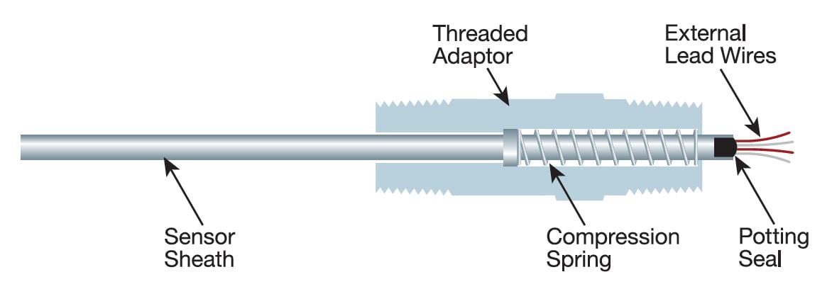
Stepped thermowells should be specified with an insertion length greater than five times the tip diameter (L/D > 5) to minimize error from heat going from thermowell tip to pipe or equipment connection from thermal conduction and an insertion length less than 20 times the tip diameter (L/D < 20) to minimize vibration from wake frequencies. Calculations by supplier on length should be done to confirm that heat conduction error and vibration damage is not a problem. Stepped thermowells reduce the error and damage and provide a faster response. Spring loaded grounded thermocouples as seen in Figure 1 with minimum annular clearance between sheath and thermowell interior walls provide the fastest response that minimizes errors introduced by the sensor tip temperature lagging the actual process temperature.
 Figure 1: Spring loaded compression fitting for sheathed TC or RTD
Thermowell material must provide corrosion resistance and if possible, a thermal conductivity to minimize conduction error or response time, whichever is most important. The tapered tip of the thermowell must be close to center line of pipe and the tapered portion of the thermowell completely past the equipment wall including any baffles. For columns, the location showing the largest and most symmetrical change in temperature for an increase and decrease in manipulated flow should be used. Simulations can help find this but it is wise to have several connections to confirm by field tests the best location, The tip of the thermowell must see the liquid, which may require a longer extension length or mounting on the opposite side of the downcomer to avoid the tip being in the vapor phase due the drop in level at the downcomer.
For TCs above 600 degrees Celsius, ensure sheath material is compatible with TC type. For TCs above temperature limit of sheaths, use the ceramic material with best thermal conductivity and design to minimize measurement lag time. For TCs above the temperature limit of sheaths with gaseous contaminants or reducing conditions, use possibly purged primary (outer) and secondary (inner) protection tubes to prevent contamination of TC element and provide a faster response.
The best location for a thermowell for small diameter pipelines (e.g., less than 12 inch) is in a pipe elbow facing upstream to maximize insertion length in center of the pipe. If abrasion from solids is an issue, the thermowell can be installed in the elbow facing downstream but a greater length is needed to reduce noise from swirling. If a pipe is half filled, the installation should ensure the narrowed diameter of the stepped thermowell is in liquid and not vapor.
The location of a thermowell must be sufficiently downstream of a joining of streams or heat exchanger tube side outlet to enable remixing of streams. The location must not be too far downstream due to the increase in transportation delay, which is the residence time for plug flow that is the pipe volume between the outlet or junction and sensor location divided by the pipe flow (volume/flow). For a length that is 25 times the pipe diameter (L/D = 25), the increase in loop deadtime of a few seconds is not as detrimental as a poor signal to noise ratio from poor uniformity. For desuperheaters, to prevent water droplets from creating noise, the thermowell must provide a residence time that is greater 0.3 seconds, which for high gas velocities can be much further than the distance required for liquid heat exchangers.
For greater reliability and better diagnostics dual isolated sensing elements can be used but the more effective solution is redundant installations of thermowells and transmitters. The middle signal selection of three completely redundant measurements offers best reliability and least effect of drift, noise, repeatability and slow response. The measurement from middle signal selection will be valid for any type of failure of one measurement. There is also considerable knowledge gained to head off problems from comparison of each measurement to middle.
Drift in the sensor shows up as a different average controller output at the same production rate assuming there is no fouling or change in raw materials. Poor repeatability in the sensor shows up as excessive variability in temperature controller output. For very tight control where the controller gain is high, sensor variability is most apparent in the controller output assuming the controller is tuned properly and the valve has a smooth consistent response.
For much more on calibration and temperature measurement see the Beamex e-book Calibration Essentials and Rosemount’s The Engineer’s Guide to Industrial Temperature Measurement.
Additional Mentor Program Resources
See the ISA book 101 Tips for a Successful Automation Career that grew out of this Mentor Program to gain concise and practical advice. See the InTech magazine feature article Enabling new automation engineers for candid comments from some of the original program participants. See the Control Talk column How to effectively get engineering knowledge with the ISA Mentor Program protégée Keneisha Williams on the challenges faced by young engineers today, and the column How to succeed at career and project migration with protégé Bill Thomas on how to make the most out of yourself and your project. Providing discussion and answers besides Greg McMillan and co-founder of the program Hunter Vegas (project engineering manager at Wunderlich-Malec) are resources Mark Darby (principal consultant at CMiD Solutions), Brian Hrankowsky (consultant engineer at a major pharmaceutical company), Michel Ruel (executive director, engineering practice at BBA Inc.), Leah Ruder (director of global project engineering at the Midwest Engineering Center of Emerson Automation Solutions), Nick Sands (ISA Fellow and Manufacturing Technology Fellow at DuPont), Bart Propst (process control leader for the Ascend Performance Materials Chocolate Bayou plant) and Daniel Warren (senior instrumentation/electrical specialist at D.M.W. Instrumentation Consulting Services, Ltd.).
About the Author
Gregory K. McMillan, CAP, is a retired Senior Fellow from Solutia/Monsanto where he worked in engineering technology on process control improvement. Greg was also an affiliate professor for Washington University in Saint Louis. Greg is an ISA Fellow and received the ISA Kermit Fischer Environmental Award for pH control in 1991, the Control magazine Engineer of the Year award for the process industry in 1994, was inducted into the Control magazine Process Automation Hall of Fame in 2001, was honored by InTech magazine in 2003 as one of the most influential innovators in automation, and received the ISA Life Achievement Award in 2010. Greg is the author of numerous books on process control, including Advances in Reactor Measurement and Control and Essentials of Modern Measurements and Final Elements in the Process Industry. Greg has been the monthly "Control Talk" columnist for Control magazine since 2002. Presently, Greg is a part time modeling and control consultant in Technology for Process Simulation for Emerson Automation Solutions specializing in the use of the virtual plant for exploring new opportunities. He spends most of his time writing, teaching and leading the ISA Mentor Program he founded in 2011.
Connect with Greg:


