The following discussion is part of an occasional series, "Ask the Automation Pros," authored by Greg McMillan, industry consultant, author of numerous process control books, and 2010 ISA Life Achievement Award recipient. Program administrators will collect submitted questions and solicits responses from automation professionals. Past Q&A videos are available on the ISA YouTube channel. View the playlist here. You can read all posts from this series here.
Looking for additional career guidance, or to offer support to those new to automation? Sign up for the ISA Mentor Program.
Erik Cornelsen’s Question
What would be a good control strategy to regulate a process in which the setpoint is continually changing?
An example of this process is seen in manufacturing plants where additives are added to the main product, while it is being conveyed, that has a change in its volume/weight/shape. There is a cascade loop where the actual conveyor material mass flow rate per second measured by a sensor sees significant variability. The secondary loop to control conveyor speed cannot keep up with the consequential continual setpoint changes.
Also, what can be done to improve the variable frequency drive (VFD) response regarding the configuration of key VFD parameters (e.g., acceleration/deceleration/VFD control mode: V/f, vector control)?
Hunter Vegas’s Answer
Based on what little I know, I would offer a couple of suggestions:
- It seems a little bit of filtering on the material flow rate would go a long way if you trying to ratio and/or dose a flow. While the instantaneous flow might be all over the place, the average flow probably isn't moving that much, so I would use a filtered mass flow as my control point.
- If you really do need that kind of tight control, then I would do something to smooth out that variability. Something as simple as a crossbar riding a few inches above the conveyor would knock off the high points and fill in the valleys, so that the mass reading would be more consistent.
- VFD settings, etc. may come into play depending on what else you are dealing with, but the items above may resolve your issues.
Pat Dixon’s Answer
This problem is very common in cascade loops, but the example given sounds like it is a calculated setpoint where additives are added as a ratio (stoichiometric) of the material flow. I will try to address each case.
Cascade loop: It will be assumed that the secondary loop (the loop which has its setpoint driven by the output of the primary loop) is well tuned and working as desired. An option in most PID implementations is for a change in error to only apply integral action, while applying other terms if there is a PV change. This may be desirable if we want to avoid big changes each time the primary makes a setpoint change to the secondary.
For the primary, we first need to ensure its settling time is tuned for a much longer response than the secondary. It is common to have a closed loop time constant for the primary loop at least 5 times longer than the secondary loop. Another important consideration is the filtering of the PV on the primary loop. We really want the primary loop to change the secondary loop only when there is a persistent and significant change in the primary PV. Proper filtering can avoid aggressively bouncing the secondary setpoint around.
Calculated setpoint: If there is a continuous flow of fluid and there are additives controlled as a ratio of material flow, there is no primary PID to tune. However, filtering the inputs to the calculation can ensure that changes are only made when there is persistent and significant change in the inputs to the calculation. This is the same principle that is applied to filtering of a primary PID loop described above. Also, the period for which these setpoint calculations should be at least 5 times the settling time of the secondary loop, in the same way as described above.
Greg McMillan’s Answer
Reducing the variability in the primary loop by conveyor design is the best option, followed by intelligent filtering of any remaining fluctuations getting a time averaged process variable that does not add appreciable lag or error in the measured mass flow rate of the primary loop. A feedforward signal added to the primary controller output based on known changes in additive feed rate can proactively correct for upsets to the mass flow rate. Also, a simple setpoint feedforward added to the secondary controller output can greatly help proactively deal with the changes in its setpoint.
The feedforward gain is in general set initially to be about half of what is estimated and is then gradually increased to ensure there is no overreaction and consequential inverse response from feedforward action. For a continually changing setpoint, it has been found that there needs to be more integral action to keep up with the setpoint changes.
I do not have much personal experience with the configuration of VFDs, but here are the best practices from the McGraw-Hill Process/Industrial Instruments and Controls Handbook, 6th Edition by myself and Hunter Vegas. Please note that they are intended for a pump with a VFD, and some of these practices may not be applicable to a conveyor.
- Use input and output chokes and isolation transformers to prevent EMI from inverter.
- Use PWM to reduce torque pulsation (cogging) at low speeds.
- Use a NEMA Design B instead of Design A motor to prevent a steep torque curve.
- Use bearing insulation or path to ground to reduce bearing damage from Electronic Discharge Machining (EDM) that is worse for the 6-step voltage older drive technology.
- Use at least 12-bit signal input cards to improve the resolution limit to 0.05% or better.
- Use drive and motor with a generous amount of torque for the application so that speed rate-of-change limits in the VFD setup do not prevent changes in speed being fast enough to compensate for the fastest possible disturbance.
- Minimize dead band introduced into the drive setup, causing delay and limit cycling.
- For tachometer control, use magnetic or optical pickup with enough pulses per shaft revolution to meet the speed resolution requirement.
- For tachometer control, keep speed control in the VFD to prevent cascade rule violation where the secondary speed loop is not 5 times faster than the primary process loop.
- To increase rangeability to 80:1, use fast cascade control of speed to torque in the VFD to provide closed loop slip control.
- Use external reset feedback of accurate and fast speed readback to stop oscillations from poor VFD resolution and excessive dead band and rate limiting in VFD configuration.
- Use foil braided shield and armored cable for VFD output spaced at least one foot from signal wires with never any crossing of signal wires, ideally via separate cable trays.
Erik Cornelsen’s Follow-up Questions
I think that all of these answers agree that proper filtering can improve this control system. Now, I have a few questions on filters:
- Filter types: Have you seen processes that use a simple mathematical average filter (i.e., calculate a moving arithmetic mean value from real values), or more advanced types of filters, like Kalman Filter?
- Filter commissioning: How are filter parameters typically commissioned (such as filter gain, number of samples to filter, execution time, etc.)? Is it to meet process quality requirements, or are there other important factors to consider?
- Filter on set-point (output): Is it advisable to use a filter to smooth only the input data, or would it be advisable, in a case like this, to also use a ramp function to smooth the changing set-point values, in relation to a specified change rate value?
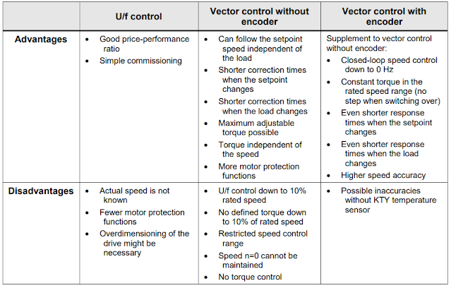
Regarding the VFD, my main concern in a very dynamic application like this is the dead time of the inverter, considering the acceleration/deceleration ramp times and the response to a set-point change that is managed by the VFD controller. In the image below from Siemens, there is a good summary of the control modes of an induction motor. This is for their inverters, but I believe that other manufacturers have more or less the same types of control modes. For a given motor without encoder, for example, it seems that vector control encoderless is, for instance, a better choice than the U/f control mode.
 Hunter Vegas’s Follow-up Answer
I have to say that when it comes to filtering, I prefer simple, out-of-the-box filtering over special advanced filters. I say this because out-of-the-box filters in DCS systems tend to work fine and when you download the module, the filter handles that automatically. If you have a special calculation to do the filtering, you have to add special software that “fills” the filter on a download so it has a current process variable in every sample. Otherwise, all the samples have zero in them, and after a download the value drops to zero and then slowly rises as the process data is “loaded in.” Personally, I wouldn’t put a filter on the setpoint as it tends to mess with the dynamics. I would start with the PV filter—that should get you what you need.
As far as VFDs/motor controls go, I find that there are two types of control applications. In most chemical plants, they are using the VFD to control a process variable (like flow or pressure), but they are using them in a relatively slow mode that doesn’t require very high-speed response. In those cases, the inverter response time really doesn’t matter a whole lot.
The other application is multi-axis control where the control system essentially acts like gears and each drive is coordinated with a master axis. In this case, the response time must be very short and servo drives are used because they are able to respond very quickly and very precisely.
Perhaps I may not fully follow your application, but from your description, it sounds like you are trying to create a very high-speed application for a process that really isn’t high speed. Yes, the process variable is bouncing around and you are trying to follow it, but the reality is that the actual mass flow rate (with a bit of filtering) probably isn’t moving much at all. Rather than filtering to get a consistent flow rate, you are trying to speed up the VFD to follow a noisy signal that is moving all over. If the conveyor mass flow really is that ugly, I expect that some small adjustments to how the material is dumped on the belt would provide a much more consistent signal that isn’t so variable (for instance, putting a small hopper between the feed belt and the main belt would eliminate the peaks and valleys and provide a more consistent flow to the belt).
In regards to vectorless control versus V/F, generally, vectorless control does work, but you have to limit the low speed to something above zero so that the motor is always moving enough to create the signal. If you don’t do that, the motor may not start.
Greg McMillan’s Follow-up Answer
I agree with Hunter that a simple PV filter is the starting point. If the PID is having trouble keeping up with the setpoint changes, I suggest first trying to increase the reset action (decrease reset time) and if that is not enough, adding a setpoint feedforward.
A second order filter or moving the average calculation can provide more attenuation of noise with less degradation of control loop performance, but the margin of improvement is maybe not worth the effort to address all the concerns that Hunter raised in terms of downloads besides the maintainability of the configuration and its parameters. I don't advise using a Kalman filter that is popular with academics because it is too dependent upon proper identification of process dynamics and can easily result in much more harm than good.
Setting a first order filter is easier than the setting of the parameters for more sophisticated filters. My general guidance for a first order filter to prevent an appreciable loss in the ability to minimize the error from unmeasured disturbances is that the filter time should not be much greater than 1/5 the total loop dead time or PID reset time setting (whichever is greater). However, getting a representative process variable in your case may justify using a larger filter time. As an example, here is a recent article on signal filtering that offers simulation results.