The following discussion is part of an occasional series, "Ask the Automation Pros," authored by Greg McMillan, industry consultant, author of numerous process control books, and 2010 ISA Life Achievement Award recipient. Program administrators will collect submitted questions and solicits responses from automation professionals. Past Q&A videos are available on the ISA YouTube channel. View the playlist here. You can read all posts from this series here.
Looking for additional career guidance, or to offer support to those new to automation? Sign up for the ISA Mentor Program.
Greg McMillan’s Perspective and Question:
The discontinuity and nonlinearity at the split range point is a major source of oscillations often leading to a limit cycle for operation near the split range point due to greater stiction and lost motion. What can be done to improve or eliminate split range control used for common applications such as fine and coarse valves and for changing from heating to cooling?
Brian Hrankowsky’s Responses:
Heating/Cooling:
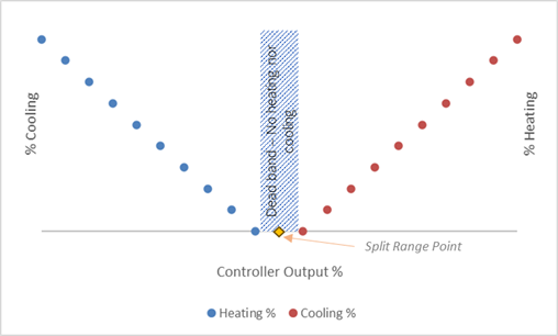
The main issue is when the system has relatively little load and hunting for a stable output near the split point of the split range. Providing a small region around the split point where no heating or cooling takes place and switching between services does not happen can allow the system to find an output that balances the system or greatly reduces the frequency of switching between services.
General:
- Consider features of the PID function that stop integral action when the loop is near the setpoint
- Design the split range so that both outputs are 0 for a small band around the split point. With digital valve controllers (DVCs), this can be 1% or smaller
- Use different tuning parameters when on the cooling vs heating side of the split or at least choose a split point that is not in the middle of the PID output range to balance the process gain as seen by the controller for the heating and cooling systems.
- Consider tuning strategies that have little to no overshoot.
- Some have found that using separate loops for heating vs cooling may not work well depending on how the PID function handles reset and rate action initialization when transitioning from the “standby loop” to the “active” loop (e.g., they may lose their “memory” and not perform well when switching).
When block valves are used to switch, which service is to be used:
- Implement a hysteresis around the split point so that the loop needs to request a certain amount of heating before the valves will actually switch.
Michel Ruel’s Responses:
Utilizing split-range strategies may give rise to several challenges.
The primary objective is to circumvent discontinuity, thereby preventing oscillations.
It is advisable to incorporate an overlap between two valves (e.g., V1 and V2) to ensure seamless continuity. In the absence of a dead band requirement, employing a characterizer for each valve becomes imperative to guarantee a continuous energy transfer.
The selection of the change point is crucial to maintaining a relatively stable process gain. For instance:
- If a 1% change in V1 results in a modification of the process temperature by 5 degrees.
- If a 1% change in V2 leads to a process temperature alteration of 10 degrees.
- In such cases, the switching point should ideally be set at around 33%, not 50%.
Exercise caution, particularly near the end of the range, especially during valve closure, as stiction tends to be more pronounced in this region.
The Human-Machine Interface (HMI) screen must be designed with clarity, displaying signals to the valve based on the established plant standards.
Implementing a coarse-fine strategy requires careful consideration.
In this approach, the flow or another variable controller assumes control over the smaller (fine) valve. A dedicated position controller is responsible for maintaining the operation of the small valve within a specified range, typically between 20% and 80%.
During the period when the small valve operates within the 20-80% range, there is no movement in the larger (coarse) valve. It remains stationary.
Once the small valve reaches either limit within the 20-80% range, the position controller becomes active, gradually adjusting the coarse valve until it falls back within the expected operational range. Following this adjustment, the position controller ceases movement to prevent potential valve defects, such as stiction or dead band.
When appropriately programmed, utilizing a PI-Gap strategy with a 50% set-point and a gap of ±30%, this approach maximizes the quality of the fine valve while leveraging the capacity of the larger valve.
PID-Gap Strategy (Most control systems provide this algorithm):
Error Handling within Gap:
- When the process variable (PV) is within the gap range (20% above and 80% below setpoint), the proportional, integral, and derivative actions of the PID controller are effectively suspended.
- The PID controller perceives an error of zero, resulting in no movement. The large valve remains in a fixed position.
Error Handling outside Gap:
- If the PV falls outside the gap, the PID controller registers an error equal to the setpoint (SP) minus PV, adjusted by the gap.
- For instance, if the PV is at 85%, the error seen by PID is 5% (the portion above the gap). This allows for smooth adjustments of the large valve to correct the deviation.
Control Impacts:
- Once the large valve has made necessary adjustments to meet capacity requirements, the PID-Gap strategy ceases all actions when the PV returns within the gap.
- Control shifts to the small valve exclusively when the PV is within the gap range.
- The advantage of this strategy is that when the large valve is frozen within the gap, any defects it may have do not influence the process, ensuring stable and controlled operation.
The PID-Gap approach combines the precision of the small valve for fine-tuning with the capacity of the large valve for broader adjustments, optimizing the control process.
If the PID gap is not offered as an option for the PID controller, it can be implemented by programming the incremental gain of the position controller (Standard or Series algorithm) so that it is zero when the position error is within the preset limits or by utilizing a dead band on position error. Note that caution is required when implementing the dead band discretely to avoid any discontinuity in action. ISA 5.9 Technical report provides useful insights regarding the implantation of deadband and PID gap.
When appropriately programmed, utilizing a PI-Gap strategy with a 50% set-point and a gap of ±30%, this approach maximizes the quality of the fine valve while leveraging the capacity of the larger valve.
See this link for ISA-TR5.9-2023 PID Algorithms and Performance Technical report
Pat Dixon’s Response: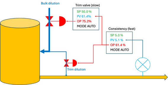
This is a very common implementation in the paper industry. Consistency is the mass fraction of solids (primarily wood fiber) in pulp. Precise control is crucial to ensure the stability of production rate, and chemical dosage, avoiding plugging of equipment or excessive drainage/drying effort. The consistency measurement is used in a PID tuned fast to throttle a small dilution valve. A bulk dilution valve is adjusted slowly to maintain the trim valve near its mid-range so that it has maximum degrees of freedom in its range of response.
Michael Taube’s Responses:
I completely agree with Michel Ruel’s assessment of split-range control caveats, especially the linearization and Human Machine Interface (HMI) representation that keeps the Operator fully informed of what the controller is doing as it moves through its output range.
The only additional comments I have regard maintenance (an often overlooked/forgotten aspect of controller design): there should be a convenient (and intuitive) means to remove a control element (valve, motor, etc.) from the control scheme to perform maintenance on that device. I usually use an AutoMan block that is accessible from the HMI for the Board Operator to access that device: setting its Mode to Manual for maintenance (as well as to stroke test it) and then back to Cascade for use by the PID controller. Of course, care must be taken that the current controller operations do not require that device to maintain its PV at/near SP and/or that alternative measures are available to do so.
One other comment I have on this topic regards the alternative approach to split-range control (not one that I recommend, but one that has come up in my career): sometimes there are more than two (2) control elements available to maintain a process measurement – one that I recall actually had FOUR! A carefully designed split-range scheme was proposed (including the maintenance aspect above as well as overlap & linearization considerations).
The client (a Process Engineer) declined this design claiming that it was “too complicated” and instead went with FOUR DIFFERENT PID controllers for the same measurement, each with different setpoints. Now the Operator was burdened with trying to manage/balance the 4 SPs such that the process measurement was nominally maintained while attempting to keep the controllers from interfering with each other. Takeaway: Trying to get a Process Engineer to grasp dynamics and control can be the greatest challenge a Process Control Engineer faces!
Peter Morgan’s Response:
Where multiple valves of equal capacity are used to share load and modulated by a single controller and individual valve position demand is determined by an offset and ranging calculation, incorporating the following features can improve operability.
Valve duty (order of opening) should be operator-selectable. This can be based on the order in which the valves are initially selected to Auto. It is recommended that the order does not change until all valves are selected to manual.
When a valve is in manual the duty of the remaining valves shifts so there is no discontinuity (gap) in control action. This can be easily accomplished by using the operating mode of the lower-order valves to determine the offset (point of opening) for each valve. Note that changing the valve offsets in this way requires the controller to be momentarily initialized to match the back-calculated total loading of all valves remaining in Auto when the mode of any valve is changed. Note that this also accounts for and accommodates the transfer of a valve to Auto at a position that is initially “off schedule”
The controller's high output limit should be calculated so that it matches the back-calculated total loading of valves that are in Auto. Although these features add complexity, once configured they are sure to win favor from operators and the technicians that service the valves.
George Buckbee’s Responses:
Split-Range control generally refers to situations where two different fluids are used to affect a common process variable. Most commonly, in a temperature loop, one fluid could be used for heating and the other for cooling. With this control strategy, management of the crossover point is critical, as mentioned by Michel and others.
Coarse-fine control, sometimes called mid-ranging control, usually involves two different-sized valves, both passing the same (or similar) fluid to the process. Pulp consistency control is a common case. In this case, there is no "crossover point". A valve position control (VPC) algorithm can be used. It is a good idea to tune the large (coarse) valve with a slower response rate than the small valve. The small (fine) valve maintains faster, tighter control over the process.
There are, of course, many other multi-valve control strategies that are not as common...maybe as many as there are control engineers!
Greg McMillan’s Follow-up:
The following are my concluding remarks from the July 2019 Control Talk Column with George Buckbee and Nick Sands titled, “Ways to Improve Split-range Control”.
Often not realized is that a deadband introduced in a PID configuration or a variable frequency drive (VFD) setup or from backlash in a control valve, will result in a limit cycle if there are two or more integrators in the control loop. Integral action can occur in many important processes (e.g., gas pressure control, and batch composition, pH and temperature control), digital positioners, and each PID in a cascade control system. Stiction requires only one integrator to develop a limit cycle.
Oscillations also break out when actuator or positioner sensitivity is poor (e.g., spool positioners and piston actuators). The good news is the oscillation period and amplitude from deadband and poor sensitivity can be reduced by more aggressive tuning and the oscillation from a splitter configuration deadband stops when the output is far enough away from the split range point.
Some companies don’t see the problem because they use control valves designed for throttling. Unfortunately, it is a more common mistake than realized to see on-off valves posing as throttling valves because the on-off valves look more attractive since they have greater capacity, much less leakage, and much lower cost. A digital positioner on these rotary valves gives a false sense of confidence because the actuator shaft position responds to the actuator. Not realized is this feedback and readback is not representative of the final control element position due to backlash in the shaft to stem and in the stem to ball or disk connection and stiction from the tight shutoff.
Right now, control valve specification sheets show capacity and leakage but not linearity, deadband, resolution, or response time. The specification sheets along with the pricing lead to the wrong choice. I have not been able to enlist general support to improve valve specification sheets to include valve response. Some astute users require valves to meet response requirements including verification by tests. ANSI/ISA-TR75.25.02 Annex A – “Valve Response and Control Loop Performance- Sources, Consequences, Fixes, and Specifications” seeks to address this need.
The nonlinearity and particularly the stiction are worse, as you might expect, near the closed position that is the split range point. Small valve drop-to-system pressure drop ratios to save energy aggravate the problem. Please, please take the time to read, understand, and take to heart “How to Specify Valves that Do not Compromise Control”. For a more succinct view, see “Is Your Control Valve an Imposter?”
To provide tight control with split ranged valves, I advocate control valves and actuators with the least deadband best resolution, and best sensitivity using a digital positioner without integral action tuned with higher gain action. I also recommend directional move suppression (DMS) which is possible for a PID with true external-reset feedback. Simply putting a setpoint up or down rate limit on an analog output block or via a rate limit block on the splitter bock input and turning on external-reset feedback (e.g., dynamic reset limit) can slow down the integral action in the direction of unnecessarily crossing the split range point.
Valve action to maintain process performance and safety would not be slowed down. (e.g., opening of coolant and vent valves would not be slowed down). For bioreactors, where pH is controlled by manipulating carbon dioxide and sodium bicarbonate, DMS would be set to slow down any increases in the sodium bicarbonate. This is critical for cell health because high sodium concentrations that can easily build up over the week-long batch increase cell osmotic pressure damaging cell membranes and leading to cell rupture.
For more on PID solutions and the power of external-reset feedback see my Shinskey tribute presentation and paper “Deep Understanding and Great Achievements in PID Control” and the McGraw-Hill 2019 Process/Industrial Instruments and Controls Handbook Sixth Edition.
The nonlinearity of the installed valve characteristic can be reduced by signal characterization. For a better appreciation of this configuration improvement see the Control Talk blog “Unexpected Benefits of Signal Characterizers”. For details on how to achieve linearization, see the Control Talk column “Why and How to Establish Installed Flow Characteristics”. For composition, pH, and temperature control, high rangeability flow meters (e.g., magmeters or Coriolis meters) can eliminate the nonlinearity seen by the primary process loops by the use of secondary flow loops.
For vessels, the need for a split range between coolant and steam can in many cases be eliminated along with the problematic phase changes by the use of steam injectors with a constant coolant flow to create a utility stream that quickly changes between cold and hot by manipulating steam flow. The PID tuning settings can be automatically updated based on which valve is being manipulated and the changes in process dynamics associated with setpoints and production rates.
For a small fine and big coarse valve, the split range point should be based on valve capacity to help linearize the open loop gain. For example, if the big valve has 5 times the capacity of the small valve, the split range point would be 20%. Valve position control (VPC) can eliminate the split range issues and can provide a faster and more precise response. The primary process controller manipulates the small valve that has a faster response time much better resolution and much less lost motion because the valve is smaller and a more desirable globe throttling valve is used with a diaphragm actuator.
The following are my concluding remarks from an August 2019 Control Talk Column with George Buckbee titled “The Best Valve Position Control”.
There are several VPC challenges to be addressed. Valve backlash and stiction are particularly an issue for the big valve being manipulated by the VPC. Big valve movement can be suppressed by adaptive tuning where the gain is nearly zero for a tolerable offset from the VPC setpoint (e.g., gap action). Backlash can be compensated for by an increment and decrement equal to the deadband for a change in signal direction that is positive and negative, respectively.
You are stuck with stiction. However, in addressing another challenge that is large disturbances (potentially causing the primary controller to manipulate the small valve to run out of valve) by adding a feedforward signal to the VPC output to preemptively position the large valve, you can increase the gain for small changes in feedforward signal to get it through the resolution limit. The positioners for both valves should not use integral action and be tuned with aggressive proportional action to minimize deadband and resolution limit seen by the VPC. External-reset feedback (e.g., dynamic reset limit) can be turned on in VPC to stop limit cycles if there is a good readback of the actual final closure element position (e.g., actual plug, ball, or disk position).
Note that shaft position feedback is often not a good indicator of actual ball or disk position for rotary valves designed for tight shutoff due to high seal friction and backlash in the ball or disk to stem and in the stem to the actuator shaft. Balls or disks with integrally cast stems and splined stem-to-shaft connections can minimize the backlash from shaft windup. See the Control Talk feature article “How to Specify Valves and Positioners that Don’t Compromise Control” to avoid this increasing problem due to the emphasis on capacity, leakage, and cost and not valve response.
Signal characterization applied to each PID output should be used to linearize the installed flow characteristic that tends to be quite nonlinear for rotary valves. This helps feedback and feedforward control. The tuning of the VPC is still a challenge even after the linearization of valves because any change initiated by the VPC has to work through the primary PID closed-loop response before it is seen as the corresponding change in the small valve position that is the controlled variable of the VPC.
Thus, the VPC tuning depends upon the primary PID tuning besides the open loop response of the process. This means the primary PID should be tuned first to provide a fast response. The VPC is then tuned to provide a closed-loop response that is at least five times slower than the primary PID. This can correspond to the VPC lambda being at least 5 times the primary PID lambda. For near-integrating and true integrating processes, the lambda is an arrest time (time to stop a process excursion from a load disturbance on process input). In a way, these rules about tuning the lower loop first for a fast response and then tuning the upper loop for a 5 times slower smooth response is like that for cascade control.
However, in the VPC case, tight control in the VPC loop is not important. If a positioner or primary PID is retuned, the VPC must be retuned. To help keep the big valve out of the picture, the VPC gain can be greatly decreased when the small valve is in a good throttle range (e.g., zero in gap control). However, the gain must be large enough to prevent violation of the minimum gain for integrating and runaway processes. In some cases, an incremental change in VPC output that is slightly less than the resolution limit or lost motion can help improve the large valve precision and response.
In general, the VPC goal is a smooth gradual optimization with a fast getaway for abnormal conditions. Feedforward, procedure automation, and nonlinear adaptive tuning (e.g., higher VPC gain as the small valve approaches the end of the desired throttle range) can be used to help prevent running out of the small valve. Directional velocity limits by putting different up and down setpoint rate limits on what the VPC is manipulating and turning on external-reset feedback is a powerful tool detailed in the ISA-TR5.9-2023 Technical Report Section 6.6.7 “Intelligent split range control” and how to get the best control valve response detailed in Annex C “(informative) Valve Positioners.”
There are many applications where VPC can optimize a process by pushing a primary PID control valve to a maximum or minimum throttle position with room to maneuver. In nearly all cases, the signal to the valve being pushed to the limit can be used instead of the actual valve position as the controlled variable of the VPC. Note that if signal characterization is applied to the VPC output, the valve signal is the characterizer output.
The Control Feature article “Don’t Overlook PID in APC” provides significant guidance on how prime mover, chiller, and cooling tower energy costs and purchased fuel and reagent costs can be minimized and how reactor and column production rates can be maximized. The ability to handle abnormal conditions by directional velocity limits, feedforward, and adaptive tuning is greater for these applications because in most cases valves are being pushed to be as far open or closed as possible without interfering with the ability of the primary PID to provide tight control.
Héctor Torres’ Responses:
A split range strategy for temperature control in extrusion processes is quite typical. The extruder barrel is often divided into various sections with both heating (electric heater) and cooling capacity (cooling water). The implementation of a small dead band around the split range point has proven to help minimize the rolling oscillations occasioned by the controller output working continually in this zone. When the controller output falls within this dead band, no heating or cooling takes place.
If the strategy cannot be implemented using the control system standard function blocks, a custom logic will be required to characterize both heating and cooling slopes properly setting the boundaries of the dead band around the split range point.
The implementation of a valve position control (VPC) strategy is a good option for applications where fine and coarse valves are to be used. The following example shows the planned control strategy for heating and cooling of a large water container where both large and small valves were to be used.
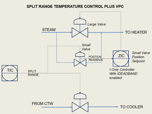
The application required to bump the temperature at the minimum time possible. It was soon realized that the VPC strategy was not adequate as it is known to be slow. The simplest solution was to implement a second splitter at the heating side of the controller.
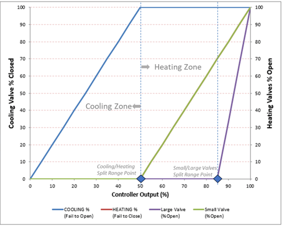
This strategy was easiest to tune. The tuning for the small valve was used as it is what is being manipulated for maintaining the temperature at the setpoint. The tuning is very aggressive for the large valve but all it means is getting to the setpoint faster and backing off the large valve sooner. The small/large valve split range at 85% gives the PID output sufficient range to stay with the small valve after heat-up. Normally a much smaller portion of the split range for the smaller valve would be allocated but having it at 85% avoids going back and forth across the split range point.