This post was written by Rick McLin, a former technical consultant with Schneider Electric.
Compressors are major pieces of capital equipment with long, effective lifespans. Unfortunately, control system obsolescence, plant reconfigurations, and changes in process requirements can all drive the need for a control system retrofit over the lifetime of the compressor, and the multivariable, nonlinear system architectures required for compressor control can cause fear and uncertainty for the engineers responsible for executing the project.

However, by avoiding fundamental mistakes during the design phase, engineers can instead consider any retrofit as an opportunity to improve compressor operation and efficiency. This article will explore major areas to make compressor control improvements, including:
- Compressor control algorithms
- Control system interactions, including capacity control
Improving compressor control algorithms
The first area to investigate is the compressor control algorithm itself. If the compressor installation is more than ten years old, the control system involved is likely based on outdated anti-surge techniques that may not be as efficient as those in common use today. With current technology, it is no longer necessary to sacrifice process stability to protect the compressor. Today’s control hardware capabilities allow the use of rigorous models to optimize compressor performance, as well as tighter integration of the compressor controls into the overall process itself.
Performance maps supplied by the compressor vendor provide the base for compressor control algorithms. These maps typically represent flow along the X-axis, while discharge pressure, pressure ratio, or head are located along the Y-axis. Engineering units used on the X- and Y-axis can be (and often are) just about anything. Indeed, the only flow measurement not previously seen seems to be cubic furlongs per fortnight—anything else is apparently fair game. A typical compressor performance map depicts a variable-speed machine with performance shown as polytropic head on the Y-axis versus flow on the X-axis, measured in thousands of cubic feet per minute. Compressor flow and pressure follow a speed line until they reach a surge point. The flows and pressures change as the speed of the compressor changes. Another set of curves defines compressor efficiency at various speeds and flows. Compressor impellers are normally designed to achieve maximum aerodynamic efficiency near the center of each speed line. If the compressor does not normally operate near its area of maximum efficiency, consider a compressor rerating.
The phenomenon of surge
Surge occurs when the kinetic energy imparted into the gas by the impeller is less than the potential energy in the discharge. When this occurs the flow of gas will reverse direction.
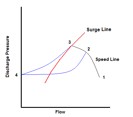 Figure 1: What happens during compressor surge
When a compressor approaches the surge point along a speed-line flow, the compressor will reverse direction. This flow reversal happens at the speed of sound, far too fast for instrumentation to detect, and, once started, cannot be stopped. A surge cycle will repeat unless the surge control system intervenes. Repeated surge cycles can seriously damage or even destroy a compressor, so predicting the onset of surge is essential in modern surge-control algorithms.