

This post was authored by Suresh P. Nair, senior engineer at BW Offshore.
This blog explores the advantages of using Foundation Fieldbus on a floating production storage and offloading (FPSO) project by analyzing the results as if it had been implemented using Foundation Fieldbus. An FPSO receives hydrocarbons from offshore subsea fields, processes the produced fluids (with provisions for storing the oil in cargo tanks for later export), and compresses the produced gas to export to a suitable infrastructure. The industrial control and supervisory system reliably supervises, manages, monitors, controls, and maintains safety.
Foundation Fieldbus technology offers advantages such as digital protocol, flexibility for design, interoperability, self-diagnostics, ease of installation, minimum cabling, easy calibration, and simple commissioning. Despite these features, this technology is yet to gain popularity in FPSO projects. This article evaluates the integrated control and safety system (ICSS) of a recently executed FPSO project that employed a combination of remote input/output and traditional hardwiring concepts against the use of Foundation Fieldbus technology for the same application.
The ICSS implemented on the FPSO is a distributed system, provided with controllers, network interfaces, and other main equipment connected together through a redundant network. The system-associated electronic cabinets are installed primarily in three different locations: the central equipment room (CER) located in the living quarters, the switchgear room (SR) located in the engine room, and the electrical power module (EPM) located in the main deck. In addition, remote input/output (RIO) panels are located on topside modules for process plant management. The central control room has operator stations for user interface, monitoring, and control of plant performance; for alarm annunciation of process systems, utility systems, and marine systems; and for attending to safety actions.
A FPSO project at Singapore Shipyard is considered for analysis purpose in this article. The FPSO conversion program includes selection of a cargo oil tanker vessel, repair and life extension of the vessel to meet the required project design life; design and installation of marine services equipment, firefighting equipment, process and utilities equipment at shipyard. The topside process modules for hydrocarbon processing and offloading/export were designed and built independently at the process module fabrication yard.
The topside process modules for hydrocarbon processing and offloading/export were designed and built independently at the process module fabrication yard. Afterward the topside process modules were transported, lifted, and installed on the main deck. Thereafter at the shipyard, the topside process modules were integrated with other services including cabling and piping. Mechanical completion includes the verification process of correct fabrication, construction, installation, inspection, testing, protection, and preservation, which are required before subsystem or system energization/pressurization and acceptance as mechanically complete. Commissioning and operation follows mechanical completion.
FPSO conversion and compliance
Upon FPSO project award, the contractor/operator prepared for repair and life extension, conversion, and then integration of new topsides equipment onto the sourced cargo oil tanker vessel. The contractor/operator was obliged to meet the design life requirements specified by the client. For the FPSO in consideration, the client specified a design life of 15 years, and engineering, procurement, construction, and operation activities were planned and executed accordingly to ensure uninterrupted FPSO operation and minimum downtime.
During the conversion and life-extension program, little of the installed mechanical equipment in the engine room, cargo tanks, and other areas that were also used for FPSO operation (consisting of instruments and controls) were serviced, tested, and calibrated for reuse, as they were found to be suitable for the new application and service requirements. It is important to note that instruments were decades old, so any advanced technology integration was a challenge. Further, the existing instrumentation and controls found faulty were renewed or replaced with identical device types. Additional instrumentation and control equipment, as required for an FPSO operation, including process production and utilities, were installed to meet service applications.
Through all stages of the vessel conversion, it was the responsibility of the main contractor to meet codes, rules, guides, standards, and other criteria set by class society to obtain the class notation FPSO. This included the compliance of the equipment and components from selected subsuppliers to the classification requirements as well.
ICSS architecture and summary
The ICSS mainly comprised the following systems with their specific interconnections as noted below:
- Process control system (PCS): For process facility monitoring and control, the inputs and outputs were hardwired to RIO or junction boxes or directly to instruments and valves.
- Process shutdown system (PSD): For detection and prevention of hazardous situations in process facilities, the inputs and outputs were hardwired to RIO or junction boxes or directly to instruments and valves.
- Vessel monitoring system (VMS): For all marine and utility system monitoring and control, the inputs and outputs were hardwired through junction boxes or directly to instruments and valves.
- Emergency shutdown system (ESD): Responding by automatic shutdown and alarms based on manual action from ESD stations, inputs were line monitored and outputs hardwired.
- Fire and gas system (F&G): Detecting fire or the presence of hydrocarbon vapor outside the pressure containment and responding with commands for the appropriate level of automatic shutdown and alarms.
- Power management system: The FPSO power management system controls and balances power generation based on power demand.
- Information management system (IMS): IMS collects and process real-time data and historical information from the network for exchange of data.
- Packaged equipment control system (PECS): To monitor packaged unit equipment information.
Table 1. The project system wide I/O's distribution summary
|
I/O summary |
||||
|
System |
AI |
AO |
DI |
DO |
|
PSD |
94 |
- |
113 |
84 |
|
PCS |
122 |
53 |
104 |
14 |
|
VMS |
72 |
13 |
402 |
51 |
Table 1 is the summary of total I/O points for the executed FPSO specific to the PCS, PSD, and VMS systems. In line with the requirements by classification society, the inputs and outputs for safety interlocks are hardwired and fall outside the scope of this analysis. Therefore ESD and F&G system are not discussed any further in this article. In addition, because the PECS is a packaged unit control system that is interfaced with ICSS with dedicated controllers and is interconnected either through hardwiring or Ethernet/serial link communication as required, it is not discussed further in this article.
This post focuses mainly on the PCS, the PSD, and the VMS and the comparison between the implementation of hardwire/RIO and Foundation Fieldbus technology, including concepts and integration issues with cases and details. The subject FPSO ICSS architecture was developed based on a distributed RIO system mounted on each process module for PSD and PCS systems. The PCS and PSD controllers were located in the electrical power module or in the central equipment room. The VMS system was located in CER and in the SR.
Area classification
The project hazardous areas were identified using the Class facilities guide and API-505. The areas were grouped to meet the requirements as follows:
- Topsides for gas Class I, Zone 2, Group II A, B or C, and temperature Class T3
- Engine room electrical, instrumentation as minimum suitable for safe area
- Cargo pump room for Zone 1, Group IIC, and temperature Class T3
- Battery room for Zone 1, Group IIC, and temperature Class T3
The complete system, including equipment supplied, circuitry design, fabrication, and installation had to meet the area classification described above.
Why Foundation Fieldbus for FPSO?
In an FPSO lease contract, the return on investment only begins after the FPSO reaches the field location. A successful FPSO project completion relies on project execution within the time specified, with sailing from the shipyard on the scheduled date, minimum time at anchorage, timely mechanical completion, commissioning of the majority of systems before the vessel reaches the field, and achieving operation readiness with no setbacks.
In many historical cases, the FPSO was delayed from the shipyard to the field because of setbacks during construction and installation after mechanical completion. The implementation of ICSS contributes significantly to the project timeline, and hence is worthy of some focus toward improvement.
When the project execution plan is laid out, it is essential to select a suitable technology early for implementing the ICSS. However, the main criteria for selecting the technology is that the project execution team is convinced and is favorably disposed toward the Foundation Fieldbus technology based on the ease of its installation, cost effectiveness of the installation procedure, and efficient achievement of mechanical completion in comparison with conventional technology. The selection of Foundation Fieldbus technology also makes documentation available early at the shipyard or topsides module construction yard. This also makes a shorter project timeline. While it is noted that hardware component cost of advanced technology is comparable with traditional wiring methods, the advantages of the advanced technology for installation prevail over the hardware component cost.
From a field-wiring perspective, there are various technologies that are advanced and advantageous, including RIO, Profibus, and Foundation Fieldbus. The Foundation Fieldbus technology, however, receives focus in this article with the following justifications.
RIO systems offer all the advantages when compared to the conventional cabling method; however, compared to Foundation Fieldbus, the RIO systems are a partial solution. Foundation Fieldbus has advanced technological features. Foundation Fieldbus and Profibus technologies are identical in many features and similarities; however, the primary difference that sets the Foundation Fieldbus devices in a favorable position is that the built-in function blocks and capacity for peer-to-peer communication between the devices with this technology can facilitate control functions and continued operations even when communications with the main control system are lost.
Foundation Fieldbus architecture fits well with a modular segmental approach and could be a major factor for efficient and timely integration of FPSO equipment and process modules with the overall ICSS. Also, the diagnostic features save labor time, shortening the FPSO startup and commissioning phase. The error-free execution of activities such as point-to-point checking, loop checking, and wiring checking helps keep the overall project on schedule.
FPSO application areas
Foundation Fieldbus technology can be implemented in five major areas in an FPSO: topsides, engine room, cargo pump room, main deck, and living quarters. Refer to figure 1 for the areas marked on the FPSO general arrangement drawing. The overview below lists the equipment systems where Foundation Fieldbus technology could be implemented for continuous monitoring, control, discrete signals alarms, and controls.
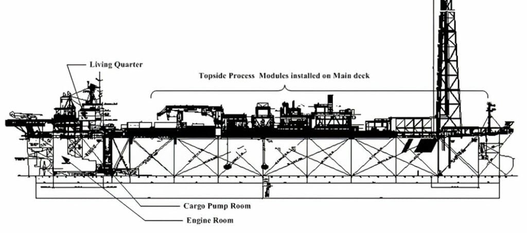 Figure 1. FPSO general arrangement drawing
Topsides
Topside modules installed on the main deck consist of process production modules such as the manifold, metering skid, flare knockout, inlet gas separation and condensate stabilization, gas compression, dehydration, chemical injection, boilers, utility, flare and vent system, and fuel gas system.
Engine room
This is a ventilated area and includes various utility systems such as air compressors, air dryers, the nitrogen generator, cooling system, diesel system, bilge system, steam system, calorifier, fresh water generator, reverse osmosis plant, hydrophore, sewage treatment plant, lift pumps, cargo pump turbine, group starters, switch gear, and essential generators installed throughout the various deck levels in the engine room. In general, the engine room is classified as a safe zone.
Pump room
This is a ventilated area and is installed with cargo pumps and ballast pumps at the lowermost deck level. This area is classified as Zone 1, and all instruments at this level are selected as intrinsically safe type.
Main deck
The main deck is installed with tank gauging level instruments, the inert-gas vent, offloading system, and fire water deluge system. The area shall be classified to hazardous area classification.
Living quarters
Living quarters consists of the central control room, central equipment room, fire dampers, the cargo control console, mess/galley, air handling units, uninterruptible power supply (UPS), and living rooms for operators and crew members.
Topology
From the list of systems above, this article will use the topsides and engine room to demonstrate the advantage of the Foundation Fieldbus technology over the hardwire/RIO configuration chosen for the subject FPSO. A combination of hardwire and RIO configuration considered the following requirements:
- The cables used were the flame-retardant type or flame-resistant type, depending on the service of application.
- Individual signals were connected through cables hardwired to either RIO or junction boxes or directly to the EPM or SR or CER where the host controllers are installed.
- Stainless-steel junction boxes were Exe-rated type and with EExd glands.
- The RIOs were suitable for use in a hazardous area and rated for IP66 weather protection requirements.
Topsides cabling
Each single pair of cables was connected to the RIO panel from individual instruments and valves at various locations in the module. The PCS signal-based inputs and outputs were connected to a PCS RIO panel and PSD signals to a PSD RIO panel. Then a redundant RIO bus network cable connected the topside process modules to the PCS controllers residing in the EPM and the PSD controllers residing in the CER. For a chemical-injection module (figure 2), the PCS-RIO and PSD-RIO were installed near the PCS and PSD controller inside the EPM. For the production-separator module (figure 3), the PCS-RIO and PSD-RIO were installed on the module and interface with the PCS and PSD controller in EPM.
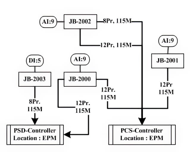 Figure 2. Installed hardwire/RIO configuration for the chemical-injection module
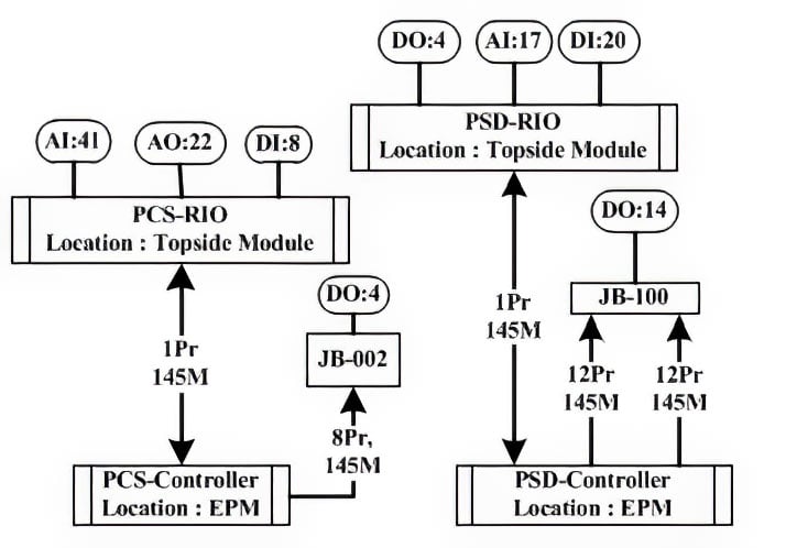 Figure 3. Installed hardwiring configuration for the production-separator module
Engine room cabling
Each single pair of cables (figure 4) was connected from each instrument either directly from the VMS system cabinet in the SR or through junction boxes and further through multipair cabling to the SR. The local control cabinet signals were connected to the VMS through multipair cables. Cabling from individual inputs and outputs was routed from each engine room deck level to the VMS system cabinet.
In the engine room, it was difficult to route the cables because of space constraints, inaccessibility, and clashes with other installed equipment.
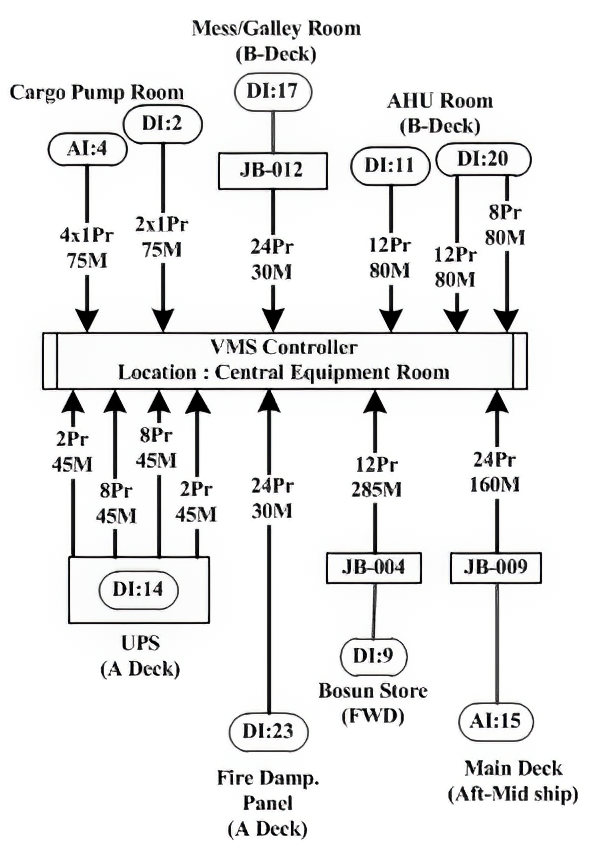 Figure 4. Installed hardwiring configuration in the engine room
Foundation Fieldbus configuration
The configuration diagrams represented here illustrate the extent of cabling and the type of cables used for handling and thereby the associated work related to interconnection. To compare the configuration of similar areas, figure 5 using fieldbus technology should be compared with figure 2; figure 6 should be compared with figure 3; and figure 7 should be compared with figure 4.
Topsides cabling
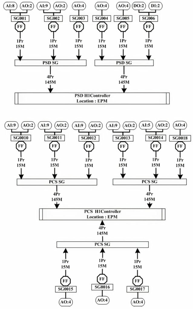 Figure 6. Foundation Fieldbus configuration on production-separator module
For comparing the hardwiring/RIO and Foundation Fieldbus configurations, the following considerations are made:
- The type of cables used is similar to the hardwire configuration.
- The areas and systems compared are for the same signals.
- The length of the spur segment is considered as the basis without the use of t-connectors (or similar connectors) or any optimization.
- The original/existing cargo tanker traditional instrument devices and control devices predominantly found in the engine room are integrated into the Foundation Fieldbus segment through gateway devices, logic transmitters, or multiplexers.
- The new instrument devices, control devices, and actuators are compatible with Foundation Fieldbus and hold interoperability functions.
- A typical segment, including input and output, shall not include more than 12 devices with no more than two output control elements. If a segment consists of only output control elements, then the segment shall not have more than four devices.
- The local control panel is prewired with segment devices within the cabinet.
- The Foundation Fieldbus intrinsically safe concept is applied for the signals from the cargo pump room.
Engine room cabling
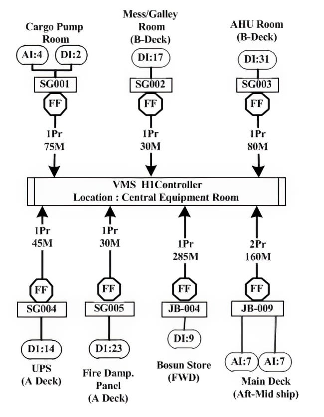 Figure 7. Foundation Fieldbus configuration in the engine room
Cost comparison
A cost comparison was made for the installation materials and works during construction at the integration shipyard and topsides module fabrication yard. It is summarized in tables 2 and 3. Table 1 is tabulated based on the installation method of figures 2, 3, and 4. Table 2 is tabulated based on the installation method of figures 5, 6, and 7.
Table 2. Installation cost of combination of hardwire and RIO configuration
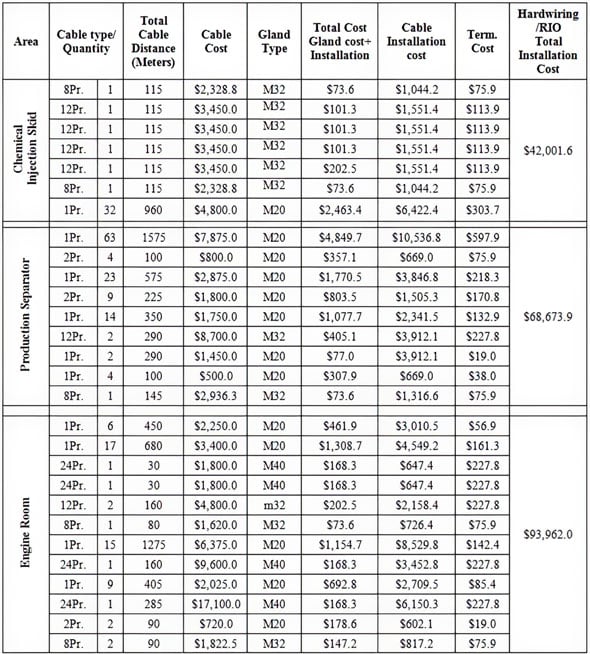
Table 3. Installation cost of Foundation Fieldbus configuration
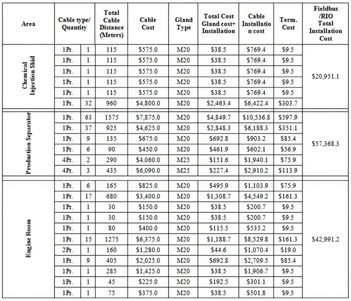
The installation cost is the shipyard estimate priced in U.S. dollars. It is noticeable from the tables above that companies can gain considerable savings from installing the Foundation Fieldbus configuration compared to the hardwire/RIO configuration.
Foundation Fieldbus advantages on overall project schedule
The Foundation Fieldbus contributions to the installation activities and the overall project schedule are significant. As a minimum, the Foundation Fieldbus technology offers these benefits:
- The Foundation Fieldbus configuration approach calls for single pair segment cables in many cases, which makes it simpler and faster to perform the cable-pulling activity at the shipyard.
- Simple cabling requires minimum manpower at the workplace and thus minimizes the safety risks at shipyards and module fabrication yards.
- Cable sourcing and management are efficient, because typical and similar cable sizes are used.
- The period for cable installation supports, welding, and other work activities relating to safety permits at the shipyard are minimized.
- The mechanical completion procedure is easier and followed by instant commissioning activities supported by Foundation Fieldbus technology, because the technology has error reduction and easy fault-diagnosis functionality.
Implementation considerations
The user may well be the FPSO operator, part of the same group that does design and support during the operation phase through the plant stabilization and maintenance phase, and in many cases through the design life. Once the organization selects the Foundation Fieldbus design option, it establishes a fundamental strategy of the design and develops system architecture, configuration details developed, front engineering/extended basic engineering to be performed at the begin of project. This needs to be explained in detail to achieve the trust of plant operations technicians by describing the comforts of the technology during operation and maintenance, diagnostics features, reliability, and accuracy and stability. It is important that FPSO operations and maintenance technicians are involved in the development of all the phases of a project.
The technicians' training program should start in the initial stages of a project. A specialist should be identified and should be part of the supplier team during the system development. This person will then gain experience with the system software versions update, debugging, and so on.
A technology supplier with FPSO projects executed experience should be chosen for implementation right away at the beginning of the project. The Foundation Fieldbus system supplier chosen shall have a competent team of engineers and technicians to ensure the ICSS configuration strategies, segment selection, methodologies, graphic displays, and historian configuration. The supplier with past project lessons learned and the action play a vital role on implementation.
The supplier should have a robust support team to ensure the successful integration and completion of the project. Further, the supplier must be capable of providing support during the operation and maintenance phase of the facility.
At the start of the project, the FPSO design contractor and Foundation Fieldbus system supplier should jointly conduct in-depth studies on those life-extension instrument items, control devices, and tests carried out. The selection of gateway devices should be tested for their compatibility.
Conclusions
Note that the FPSO return on investment is of prime importance. This begins from the time the vessel conversion has been completed, and the FPSO has been tested and deployed at the designated offshore field location. It pays if the technology applied on the FPSO takes into account minimum work at the shipyard and the ease of testing installed systems. The technology selected for implementation should be able to accelerate the project execution and meet the desired timelines.
As cited in the above tables from a real project reference and the Foundation Fieldbus approach, the installation cost and cabling efforts are less for the Foundation Fieldbus configurations as compared with other current practices for FPSOs. Selection of technology should not be limited to a cost comparison of the hardware components and additional engineering efforts between available technologies in an FPSO integration project. The segmental approach of the Foundation Fieldbus configuration is well suited to an FPSO project that follows a modular construction method.
The advanced diagnostics of the Foundation Fieldbus configuration, along with other latest technology features, greatly assist and augment completion formalities. The technology supports the timely completion of activities well within sail off and could also be instrumental in ensuring smooth startup activities.
About the Author
Suresh P. Nair is senior engineer at BW Offshore, Singapore. As a lead engineer, he has executed several FPSO projects and has held various responsibilities through the projects: basic design, detail engineering, construction, and start-up. He has more than 25+ years of experience and holds a master's degree in control systems and automation.
Connect with Suresh![]()
A version of this article also was published at InTech magazine.
