

This post was written by Scott Stewart, senior product consultant with Yokogawa Corporation.
Electromagnetic flowmeters, or as they are known by their more common name, magmeters, have become one of the most common flow metering technologies over the past 50 or more years. They are simple to operate, have no moving parts, cause no flow obstruction, and can provide a high level of accuracy and turndown ratio. The only hard-and-fast rule of application is the process liquid must be electrically conductive.
Simple working concept
High school physics tell us that a conductor passing through a magnetic field will generate a voltage that is proportional to the speed with which the conductor is moving. You might recognize it as Faraday’s law of magnetic induction.
In the case of a magmeter, the liquid itself is the conductor, and the magnetic field is created by coils placed around the pipe. Two electrodes placed on opposite sides of the pipe perpendicular to the liquid flow and the magnetic poles measure the induced voltage. The voltage generated is proportional to the velocity, which is then converted to a flow rate. The liquid flow, magnetic field, and line between the electrodes form the x, y, and z axes.
Figure 1 goes into more detail about the actual construction. Magmeter users appreciate how the interior surface of the device can match the upstream and downstream pipe diameter, and how there are no obstructions into the flow stream. The flowmeter itself must have an insulating lining, which can be made from rubber, Teflon, ceramic, or other materials capable of standing up to erosive or corrosive media.
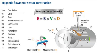 Figure 1. Magmeter construction is very straightforward. The magnetic flux field (B) is generated by a coil that is mounted perpendicular to what are typically two electrodes. They will pick up the induced electromotive force (voltage). The magnetic field generates an electromotive force proportional to the magnetic flux density (B), the velocity of the conductor (V), and the diameter of the pipe (D).
Magmeters are highly scalable, running from 0.1 inch to 104 inches or more in diameter. They work well for clean fluids, such as water, acids, and caustics—or in heavy particulate applications, such as paper stock, pulp, and lime slurries. As mentioned earlier, the main requirement is the process media must have some level of conductivity, with a typical minimum range of 1 micro-Siemen (µS) to 5 µS. As long as the process meets this requirement, the meter should perform satisfactorily in the application. Most oil-based liquids are not conductive, which knocks magmeters out of many refinery applications.
The exciting part
Since their introduction in the 1950s, magmeters have evolved enormously from a technology standpoint. A typical meter from the first decade would have used AC to excite the coil, so it used the available electrical line frequency of 50 Hz or 60 Hz. Users soon found the high sampling rate this frequency offered to be particularly well suited for noisy slurry applications, and it offered fast response to changes in flow rate. However, users also noticed these AC-powered magmeters did not have a stable zero point when there was no flow. If nothing was moving in the line, the devices tended to wander. They also used a large amount of energy, with many units drawing as much as 300 W.
As magmeter technology advanced, the next generation excited the coils with pulsed square-wave DC operating around 6.25 Hz to 11 Hz. This worked well enough in most situations and delivered the sought-after zero stability, but lower excitation frequencies could not handle noise caused by a high solids content. The low sampling rates also made them sluggish when responding to rapidly changing flow rates.
As new power supply circuits developed, instrumentation designers had more options available to try different excitation frequencies. This led to adjustable sensors where a user could choose the best frequency for the application. If the process is noisy with slurries or flow rates change rapidly, the user chooses a high frequency. For an intermittent process, such as a batch application with periods when flow stops, the user chooses the low frequency.
This approach works, but as transmitters got smarter, it was possible to incorporate circuitry capable of using both frequencies simultaneously. Dual-frequency excitation allows the transmitter to superimpose two frequencies on top of each other at the same time (figure 2). A low-frequency component of 6.25 Hz and a high-frequency component of 75 Hz work together for higher performance than either one functioning alone (figure 3).
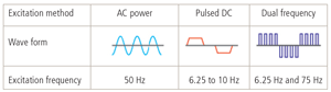 Figure 2. Creating a waveform with characteristics of both AC and DC allows a magmeter to use the advantages of both.
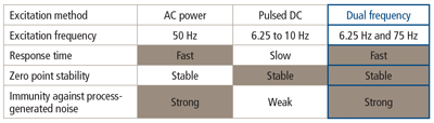 Figure 3. Dual-frequency sensors deliver performance advantages without requiring a user to choose one or the other or to switch at various points.
Reducing power consumption
Early magmeters needed a powerful magnetic field to create a signal strong enough to be measured accurately and linearized enough to provide a reliable and accurate flow reading. This is why early units drew so much power. With improvements in transmitter designs, it became possible to scale everything down, even while improving performance.
Units that once drew 300 W can now operate with 10 W to 15 W. Naturally, the physical size of a sensor has a major influence on power consumption; a 36-inch sensor requires more power to maintain a magnetic field than a 4-inch sensor. Some designs go even further with power reduction, to the point where two-wire, loop-powered designs are available in sensor sizes up to 8 inches. Bear in mind, when only 0.3 W is available (0.1 percent of what earlier units often needed), there is some compromise in performance.
Nonetheless, being able to replace other loop-powered flowmeters with a magmeter offers compelling advantages. Differential pressure and mechanical flowmeters are still very common, but obstructions in the flow path can cause clogging and pressure loss. Having the free flow of a magmeter without needing to update wiring is very attractive.
These low-power units have some limitations. Check with your supplier, but they typically require relatively high conductivity (10 µS to 20 µS) for the process liquid and a slight reduction in accuracy. Four-wire magmeters are usually capable of accuracies of ±0.2 percent to ±0.5 percent of flow rate. Loop-powered magmeters usually start at ±0.5 percent of flow. Moreover, four-wire units have a higher effective turndown ratio, handling liquid velocities ranging from 0.33 feet per second (fps) to 33 fps.
Simple installation requirements
Magmeters have few installation constraints, but observing them goes a long way toward ensuring the best possible performance. First and foremost is keeping the pipe full of liquid. If long horizontal runs accumulate slugs of air, this will cause inaccurate readings. Keep the sensor at a low point in the piping, or better yet, install it in a vertical section with flow going up.
Second, like most flowmeter designs, having straight pipe upstream and downstream from the sensor reduces turbulence and provides more accurate readings. The flow profile through a pipe is never entirely uniform, but reducing turbulence keeps it more predictable. Having at least five diameters of straight pipe upstream and at least two diameters downstream will be a major help. Having longer straight runs is even better.
No single flowmeter technology is truly universal. Every flow instrument has its limitations, so every application has to be evaluated carefully to ensure the appropriate process requirements are met. Magmeters are particularly well suited to situations with difficult liquids or where solids tend to cause clogging, so make sure they are in your application toolbox.
About the Author: Scott Stewart has been a senior product consultant with Yokogawa Corporation for 11 years, part of a 25-year career in industrial automation. Prior experience includes 10 years with Magnetrol International as a level and flow specialist in the southeast U.S. He graduated from Texas State University with a degree in marketing. Stewart is currently training for the Ride the Rockies Bicycle Tour in Colorado and likes to tinker with classic automobiles.
Connect with Scott:![]()
![]()
A version of this article also was published at InTech magazine.
