ISA Interchange

Welcome to the official blog of the International Society of Automation (ISA).

This blog covers numerous topics on industrial automation such as operations & management, continuous & batch processing, connectivity, manufacturing & machine control, and Industry 4.0.

The material and information contained on this website is for general information purposes only. ISA blog posts may be authored by ISA staff and guest authors from the automation community. Views and opinions expressed by a guest author are solely their own, and do not necessarily represent those of ISA. Posts made by guest authors have been subject to peer review.

All Posts

Primer: Distillation Column Loop Tuning


This post was authored by Harley Jeffery, who has worked in the field of industrial process control for more than 40 years. He is the author of the ISA book, Loop Checking: A Technician’s Guide.


Controlling distillation columns is a tough assignment due to the interacting nature of the process and the upstream/downstream effects of loop tuning. In this example, the column bottoms level control had stability problems (cycling), causing manual operation and the operators’ constant attention.

The bottoms level needed to be controlled to a set point that minimized the time the liquid sat in the receiver for quality purposes. However, it had to maintain a fairly tight range to prevent flooding the bottom tray on the range upper end and to maintain sufficient pump suction head for the bottoms pump out for the lower constraint.


The bottoms level needed to be controlled to a set point that minimized the time the liquid sat in the receiver for quality purposes. However, it had to maintain a fairly tight range to prevent flooding the bottom tray on the range upper end and to maintain sufficient pump suction head for the bottoms pump out for the lower constraint.

Previous loop tuning had resulted in excessive movements to the bottoms flow that adversely loaded the downstream column. Thus, the operators ran the level-to-flow cascade control loops in manual and constantly manipulated the outflow to maintain the bottoms level within the desired range. Of course, as other matters required operator attention, the bottoms level would drift. When the operator intervened for the required correction, the resultant upset of the columns affected production rate and quality.

Discussions with operating personnel revealed that they typically let the level float within a “comfort” range, because the process would fluctuate but not to the point of concern. If it looked like an up or down trend was developing, then a small bump was made to the outlet flow, and they waited for correction. If the deviation from set point became greater, then larger bumps to the outflow were performed, and they again waited for correction. When asked to place the level/flow in cascade operating mode, the level loop would typically overcorrect and begin to cycle. The outlet flow loop was considered to be working well even though it was manipulated in manual.

The operators had learned from experience what appeared to be a nonlinear gain control strategy. Trusting their judgment, we then proceeded to verify the basics before implementing the strategy.

Basics: Loop tuning and performance

Plant walk through

The first step for loop performance benchmarking is walking through the process to investigate the type and installation of the process measurement and final control elements. Then, returning to the control room, we recorded the distributed control system (DCS) control strategy and tuning. The loop inspection data forms were used to document the as-found control. The measurements were selected with the latest technologies and appeared to be installed with good practices. The control valves were a high-performance design and offered no constraints to push loop response if needed. The as-found tuning parameters were questionable and therefore confirmed our process of “verifying” base-level loop performance.
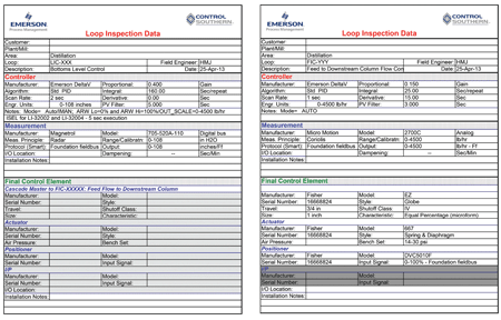
 

Figure 1. Loop inspection data forms


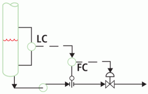
The DCS configuration application was traced to verify a typical level-to-flow cascade strategy. The DCS also has several built-in cascade application enhancements that we activated.


Bottoms level-to-flow cascade strategy Figure 2. Bottoms level-to-flow cascade strategy


Designing and testing

Verifying performance begins with designing the loop tests, which include gathering time series data of the process measurements to analyze the overall process trends, statistics for variability, and response to upsets. Then we perform individual loop bump tests to gain process dynamic data and valve performance. We elected to use the EnTech Toolkit to collect, analyze, and help tune the control loops. However, this plant uses Foundation Fieldbus, which communicates digitally to the DCS. The toolkit requires a voltage signal for the process inputs. A recently added feature of the DCS uses characterizable I/O modules, so they were employed to read the process variables over the DCS communications structure and reproduce the values on analog output (AO) modules. The toolkit was then connected to these AOs and successfully able to collect pertinent process data from the DCS.
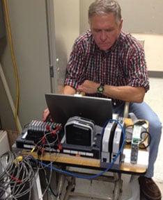
 

Figure 3. Collecting analog data from Foundation fieldbus devices


With the toolkit gathering process data, we could collect time series short-term data and overnight runs for longer-term data and saw the disturbance to the level and various operator responses. The loop bump testing confirmed that the slave flow loop was capable of aggressive tuning with good response to 0.5 percent bumps (Figure 4).


Figure 5. Nonlinear gain algorithm (NLG)


Loop tuning and verifying performance

The flow loop was retuned with the new parameters to minimize delay in response to the master level control. With the flow loop in cascade mode, the level output bumps verified and integrating process with a long dead time. The level controller was retuned with increased gain and very slow reset. With the revised tuning, the level controller was then put in automatic with the flow loop in cascade. We monitored the performance. The results showed cycling was minimized, and the set point was maintained within the desired limits.

However, the standard proportional, integral, derivative (PID) level-to-flow cascade manipulated the flow to maintain the set point with the same response for small deviations, as well as larger ones. This degree of flow change to the downstream movement caused disturbances to the highly interactive distillation process.

Advanced control (trusting the operator)

The question then became how to maintain an acceptable bottoms level while minimizing downstream disturbances caused by outlet flow changes. Returning to the operator’s method—manually making small changes to the outlet flow to maintain the level within a “comfort” band around the set point and only making larger flow changes if the level was approaching a constraint—had the benefit of minimizing flow disturbances to the downstream column.

The operator method looked like a good example of the nonlinear gain control algorithm (figure 5). This technique uses a “gap” around the set point where small gain is in effect. This is equivalent to the operator not changing the outlet flow if the level is within his or her comfort zone. However, as the PV-SP error increases, the gain is increased to make the appropriate correction; again, as the operator sees that the level is, in fact, headed to a constraint, then additional outlet flow is used to correct the level.

The DCS has a built-in NLG function that can be “enabled” on the PID algorithm:

The DCS has a built-in NLG function that can be “enabled” on the PID algorithm:

  • NL_MINMOD is the gain applied when the absolute value of the error is less than NL_GAP. To get deadband behavior, set NL_MINMOD to 0.
  • NL_GAP is the control gap. When the absolute value of the error is less than NL_GAP, KNL = NL_MINMOD.
  • NL_TBAND is the transition band over which KNL is linearly adjusted as a function of error.
  • NL_HYST is a hysteresis value. Until the absolute value of the error exceeds NL_GAP + NL_HYST, KNL = NL_MINMOD. Once the absolute value of the error has exceeded NL_GAP + NL_HYST, the absolute value of error must return to a value less than NL_GAP before KNL returns to a value of NL_MINMOD. If NL_GAP is 0, then the value of NL_HYST has no meaning (effectively assumed to be 0).

We then enabled this feature and collected additional data/observations in order to tune the gap, transition band, min mod (gain), and hysteresis. In general, we tried to mimic the operator’s method and add a smoother implementation of the flow set point changes.

ResultsPlacing the bottoms level “master” controller to automatic and the “slave” outlet flow controller to cascade with the nonlinear gain enabled and tuned, the level was maintained with acceptable limits around set point while minimizing the flow to the downstream distillation process. Recent follow-up with the plant site indicated that the loops are still in automatic, allowing operators to spend time in more productive efforts.

For additional reference, see the ISA book Loop Checking: A Technician’s Guide.


About the Author
Harley Jeffery has worked in the field of industrial process control for more than 40 years, starting with Fisher Controls as a valve application engineer. He has been a control systems engineer and engineering manager with Control Southern for the past 34 years. His experience includes design, implementation, testing, startup, and ongoing improvement of DCSs. Jeffery received a BSIE from Louisiana State University.


Connect with Harley
LinkedInEmail


A version of this article also was published at InTech magazine


Related Posts

How Did Automation Professionals Benefit from ISA in 2024?

The International Society of Automation (ISA) is proud to be the professional home of thousands of member...
Kara Phelps Dec 17, 2024 9:30:00 AM

Ensuring RCM or DCS Redundancy and Its Security in a Complex Industrial Environment

In industrial automation, remote control managers (RCM) or distributed control systems (DCS) are critical...
Ashraf Sainudeen Dec 13, 2024 10:00:00 AM

ISA Podcast Explores Automation and Smart Agriculture

The International Society of Automation (ISA) podcast, Podomation, curates and shares insightful discussi...
Kara Phelps Dec 10, 2024 11:00:00 AM