The following discussion is part of an occasional series, "Ask the Automation Pros," authored by Greg McMillan, industry consultant, author of numerous process control books, and 2010 ISA Life Achievement Award recipient. Program administrators will collect submitted questions and solicits responses from automation professionals. Past Q&A videos are available on the ISA YouTube channel. View the playlist here. You can read all posts from this series here.
Looking for additional career guidance, or to offer support to those new to automation? Sign up for the ISA Mentor Program.
Matthew Howard’s Question:
What does a good loop optimization program look like in a real mill? Suppliers are quick to sell loop monitoring software, but what do real mills do to successfully maintain critical and non-critical loops in the mill? How is it organized, staffed within the company? It would be helpful to understand ideas on basic levels. Not all industries have the same resources. So, what are the base level practice, best practice, and ideal practice?
Michel Ruel’s Responses:
Matthew, you are right, you need a plan and you need support from management. See these two Control Talk Columns: Want to be a hero? And Keys To Optimization Project Success.
Each plant is different. If you do not have the tools but you have the stamina, go ahead! I would suggest to commence to optimize a simple process control area or even a single process control loop. If you select correctly this first micro project you can demonstrate the value. You need to identify a part of the process where optimization will generate benefits.
You need to be able to calculate the value. Reducing variability is great. Improving throughput is good. Better quality is also another one but if you cannot attach a value to the improvement, you cannot demonstrate the value of your work. Discuss with operation managers, operators and others to identify a problem, losses. Here is an example:
In a pulp mill the consistency of the pulp was not stable and the paper mill complained that the number of paper breaks on the paper machine was too high. The process control engineer reviewed the control strategy (cascade), the equipment (valve and transmitter) to validate the strategy and the equipment. Then the loops were tuned (any method or tool is adequate at this stage if you understand he process and the objectives).
The horizon to determine the results was fixed to two weeks (and ensuring that no other change occurred in this process (nor mechanical, nor process, nor fiber supply). The paper mill manager computed himself the benefits and estimated that the gains of reducing the number of sheet breaks was sufficient to repay the cost (less than three days work) within less than one day. Guess what? This manager asked for more and built an optimization plan.
Hence the idea is to start with something small, low cost and demonstrate the benefits unless your management is already convinced on the benefits—which is rare. I hope that it will help! Have fun!
More on Control Performance Monitoring:
If you are a manager, you need to look at the problem at a higher level. In fact the key is not the tool itself. Some of these tools calculate over 50 KPIs—which is way too many. The issue is not the numbers of KPIs but how you manage a few of them.
Interesting to think about performance now that I’m retired and consult only occasionally—no longer in the heat of the moment and no longer having to convince plant managers of the virtues of optimization, I see the problem at a higher level view.
My suggestions is that few is better, not looking for quantity but quality. I always suggest selecting few indices. The basic ones can be implemented in your historian but software tools are available to better manage performance.
For example, indices to estimate if the process control is used:
- Loop in higher state (e.g. Cascade, Auto, Tracking, Manual)
- PV or Output is saturated
- Operator activity (mode changes, SP changes)
Indices to estimate performance:
- Oscillations detection, period of oscillations
- Noise level
- Variability or other statistics
- Settling time
Indices to monitor equipment performance:
- Valve travel
- Valve stiction
- Analyzer and soft sensors
See the article on Best Practices on Control Performance Monitoring and on PID Loop Monitoring.
Greg McMillan’s Answers:
I developed a block in DeltaV that will automatically compute peak error, integrated error with a forgetting factor, rise time, overshoot, undershoot, and settling time. The block takes into account whether the PID is auto mode and whether setpoint changes have been made. This is particularly important for startup and transitions including procedure automation in continuous operations and for the sequencing in batch operations.
These performance metrics as well as statistical metrics and the merits of procedure automation are detailed in the sections I wrote in the recently completed ISA-TR5.9 Technical Report on PID Algorithms and Performance. If you are an ISA member, you can view ISA technical reports for free.
I have also recently written an Annex A for the ISA-TR75.25.02 Technical Report on Valve Response Measurement that details the effects of not only the resolution limitation from stiction but also the lost motion from backlash and shaft windup commonly seen in rotary valves designed for tight shutoff.
Limit cycles occur for resolution and lost motion if there are more one integrator and more than two integrators, respectively, in the control loop whether in the positioner, process, or a cascade of PID controllers. The highlights or lowlights of valve response was added to an Annex C on Valve Positioners that I wrote for ISA-TR5.9.
ISA-TR5.9 also reveals that automatically measuring the loop dead time opens up the door to a lot of recognition of what the PID can do (e.g., ultimate limits to peak and integrated error) and what is possibly wrong in terms of filter times, execution times, damping settings, valve response (e.g., resolution and lost motion), and sensor response (e.g., fouling).
So far as slow oscillations, the causes are often too much integral action or limit cycles due to resolution limits (e.g., stiction) and due to lost motion (e.g., backlash) when there are one or two or more integrators, respectively in the control loop (positioners, controllers, process). Resolution limits and lost motion occur principally in control valves but can occur in variable frequency drives (VFDs) due to insufficient bits in VFD signal input cards and dead-band settings in the VFD setup.
People tend to use too much integral action because it behaves the way they would in not proactively reversing the direction of the manipulated variable until the error changes sign to deal with the inevitable dead time in the loop response. If there is an oscillation, people tend to think the cause is too much gain action.
If the oscillation period in the process variable is more than 10 times the dead time, the cause is most likely excessive integral action. If the amplitude is relatively constant and the period is between 10 and 30 times the dead time, the cause is most likely resolution or lost motion.
If the limit cycle amplitude can be decreased by increasing the PID gain, the cause is most likely lost motion. If the period is approaching or exceeding 40 times the dead time in a lag dominant, integrating, or runaway process, the cause is most likely the product of the PID gain and reset time being too small most often caused by an integral time too small but in some cases a PID gain too small. I have often seen where the integral time needs to be increased by more than an order of magnitude for these processes.
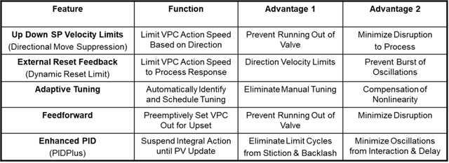
There are a lot of opportunities for optimizing processes with PID controllers. The Control Global article “Don’t Overlook PID in APC,” provides a summary of the techniques and PID features that I have used. Here are the tables currently missing from the online version:
Table 1- Examples of Optimization by Valve Position Control (VPC)
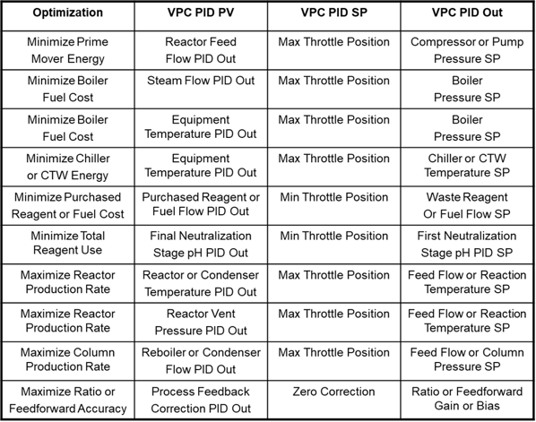
Table 2- Key PID Features for Valve Position Control (VPC)