This post was written by Greg McMillan, industry consultant, author of numerous process control books, 2010 ISA Life Achievement Award recipient and retired Senior Fellow from Solutia Inc. (now Eastman Chemical).
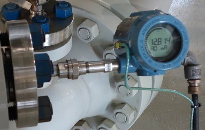
In industrial environments, high process temperatures, pressures, and vibration make it necessary to have a robust temperature sensor. Fast response time, accuracy, and stability are also needed. While several types of temperature sensors are available, such as thermistors, infrared pyrometers, fiber optic, and others, the two most commonly used in the process measurement industry are resistance temperature detectors (RTD) and thermocouples (TC).
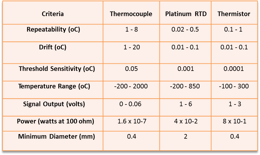
The RTD provides sensitivity (minimum detectable change in temperature), repeatability, and drift that are an order of magnitude better than the thermocouple, as shown in Table 1-1. Threshold sensitivity and repeatability are two of the three most important components of accuracy. The other most important component, resolution, is set by the transmitter. Drift is important for extending the time between calibrations and the temperature loop running at the right setpoint.
This insight was adapted from Greg’s book, Advanced Temperature Measurement and Control.
The data in this table dates back to the 1970s and consequently doesn’t include the improvements made in thermocouple sensing element technology and premium versus standard grades. However, the differences are so dramatic that the message is still the same. The temperature range shown for the RTD in the table is optimistic. At temperatures above 500°C, changes in sensor sheath insulation resistance have caused errors of 10°C or more. There are many stated advantages for thermocouples, but if you examine them more closely you realize they are not as important as perceived for industrial processes. Thermocouples are more rugged than RTDs.
However, the use of good thermowell designs and good installation practices makes an RTD sturdy enough even for high-velocity streams and nuclear applications. Thermocouples appear to be less expensive until you start to include the cost of extension lead wire and the cost of additional process variability from less sensor sensitivity and repeatability. The case of using TC or RTD input cards in a distributed control system (DCS) is not considered because of the error introduced by these input cards as a percent of span is large and individual sensor offset and drift errors cannot be individual corrected as they are with a dedicated temperature transmitter.
The IEC 751 standard describes an ideal relationship between the resistance of a platinum RTD and the temperature to which the RTD is subjected. The difference between the actual RTD curve and the ideal RTD curve results in a measurement error, which is referred to as a sensor interchangeability error. The Callendar-Van Dusen equation offers an alternative to the IEC 751 standard.
This equation can be programmed into a transmitter so that the transmitter can use the actual RTD curve rather than an ideal curve (e.g., IEC 751 standard) to translate the sensor’s resistance signal into a temperature value. The Callendar-Van Dusen equation enables the transmitter calibration to be matched to the sensor. When a sensor is replaced the parameters for the equation are entered into the transmitter. The main reasons for selecting RTDs or T/Cs can be summarized in the following lists. In all cases, field temperature transmitters are assumed to be used rather than DCS TC or RTD input cards.
You should now recognize the importance of drift, threshold sensitivity, repeatability and range in the selection of temperature sensors. This knowledge provides the fundamental essential first step that sets a control loop’s ability to keep temperatures and consequently many compositions at their optimum operating point. The principles here can be extended to other sensors. In the next post we will take a look at the next step, which is sensor installation.