AutoQuiz is edited by Joel Don, ISA's social media community manager.
This automation industry quiz question comes from ISA's technical training course, PLC Fundamentals for the Technical Professional (TC40). This course focuses on the role the programmable logic controller plays in the design of a control system and how proper selection, installation and maintenance can reduce operating costs and improve performance. It provides the technical expertise necessary to install, perform routine programming and maintenance and apply proper troubleshooting and configuration techniques.
a) control relay coil
b) output terminal energize
c) timer coil
d) motor coil
e) none of the above
Here's the answer to the quiz question from ISA's technical training course, PLC Fundamentals for the Technical Professional (TC40).
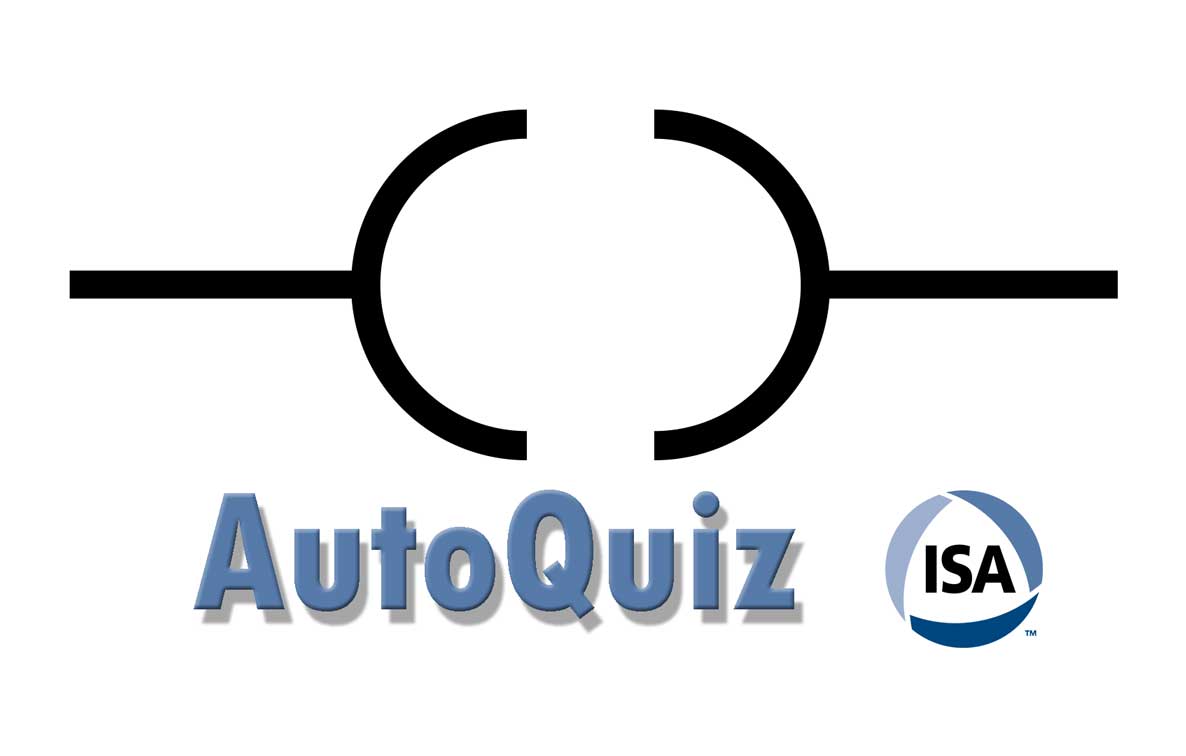
The symbol is used to represent the “On” or “Off” condition for a discrete output. The “output status” is a “1” if the ladder logic evaluates as true and is a “0” if the ladder logic evaluates as false. Output terminal energize is defined as follows: Turns a bit on or off. Use OTE instruction in your ladder logic to turn a bit when rung condition is evaluated as true.
The correct answer is B.
About the Editor
Joel Don is the community manager for ISA and is an independent content marketing, social media and public relations consultant. Prior to his work in marketing and PR, Joel served as an editor for regional newspapers and national magazines throughout the U.S. He earned a master's degree from the Medill School at Northwestern University with a focus on science, engineering and biomedical marketing communications, and a bachelor of science degree from UC San Diego.
[dropshadowbox align="none" effect="raised" width="auto" height="" background_color="#DDDDDD" border_width="1" border_color="#DDDDDD" rounded_corners="false" inside_shadow="false" outside_shadow="false"]AutoQuiz is edited by Joel Don, ISA's social media community manager.[/dropshadowbox]
Today's automation industry quiz question comes from ISA's course, PLC Fundamentals for the Technical Professional (TC40). This course focuses on the role the programmable logic controller plays in the design of a control system and how proper selection, installation and maintenance can reduce operating costs and improve performance. It provides the technical expertise necessary to install, perform routine programming and maintenance and apply proper troubleshooting and configuration techniques.
a) control relay coil
b) output terminal energize
c) timer coil
d) motor coil
e) none of the above[dropshadowbox align="center" effect="raised" width="500px" height="" background_color="#fffdb5" border_width="1" border_color="#DDDDDD" rounded_corners="false" inside_shadow="false" outside_shadow="false"][expand title="Click Here to Reveal the Answer"]
Here's the answer to the quiz from ISA's course offering, PLC Fundamentals for the Technical Professional.
The symbol is used to represent the “On” or “Off” condition for a discrete output. The “output status” is a “1” if the ladder logic evaluates as true and is a “0” if the ladder logic evaluates as false. Output terminal energize is defined as follows: Turns a bit on or off. Use OTE instruction in your ladder logic to turn a bit when rung condition is evaluated as true.
The correct answer is B.
[/expand][/dropshadowbox]